Following is the tutorial of a DIY intelligent uninterruptible power supply (UPS) for a Raspberry Pi or similar single-board computers. It provides backup power and enables a safe system shutdown upon power failure.
The purpose of the UPS is to provide the Raspberry Pi server with backup power in the event of mains power failure. The Raspberry Pi periodically reads the status of the UPS over the USB to serial interface, logs the power failure events and initiates a safe system shutdown if the UPS runs out of battery power.
This device is suitable for any single-board computer running on 5 Volts with a maximum of 2.5 Amperes of current consumption.
Warning: this project implements a software based Lithium-Ion battery charger. Lithium-Ion batteries are hazardous devices. Overcharging, short-circuiting or otherwise abusing Lithium-Ion batteries may result in a fire and/or a violent explosion. The author of this page neither takes any responsibility nor can be held liable for any damage caused to human beings and things due to the improper handling of Lithium-Ion batteries. Please be aware that the current design has not been certified for safety, consequently it is not suitable for commercial applications and must be implemented at your own risk. Last but not least, it is imperative to equip the Lithium-Ion battery with a dedicated off-the-shelf battery protection circuit.
Table of Contents
Theory of Operation
The UPS is built around an Arduino Pro Mini compatible board featuring an ATmega328P microcontroller. The backup battery consists of two 18650 Lithium-Ion (Li-Ion) cells connected in parallel. Each of the cells is protected against overcharge and over discharge by its dedicated battery protection circuit. A very efficient DC-DC boost converter is used for converting the battery voltage ranging between approximately 2.5 V and 4.2 V to the 5 V required by the Raspberry Pi and its peripherals.
The Raspberry Pi communicates with the UPS using the virtual serial port provided by a USB to serial converter. The serial port is used by the Raspberry Pi for sending text messages over the command-line interface (CLI) and for uploading firmware to the UPS. The Python script ups.py running on the Raspberry Pi periodically polls the UPS to get the system status and write the latter into the event log.
A Lithium-Ion battery charger implemented in software on the Arduino takes care of trickle charging the battery while limiting its maximum voltage in order to extend the battery service life.
State Machine
The business logic of the UPS is implemented as a state machine who’s states are shown in the table below.
| State | Description |
|---|---|
INIT | Initialisation state executed upon initial boot |
EXTERNAL | External power is fed into the Raspberry Pi. |
BATTERY | Battery power is fed into the Raspberry Pi. |
ERROR | Error condition due to very low battery voltage, faulty DC-DC converter or EEPROM CRC check failure. External power is selected and battery charging is disabled. |
CALIBRATE | Calibration mode where external power is selected and battery charging is disabled. This mode is used as part of the calibration procedure described later in this article. |
The Arduino monitors the following metrics for selecting the appropriate state:
 : voltage of the external power supply
 : voltage at the DC-DC converter output
 : battery voltage
The figure below shows the state machine diagram of the UPS device.
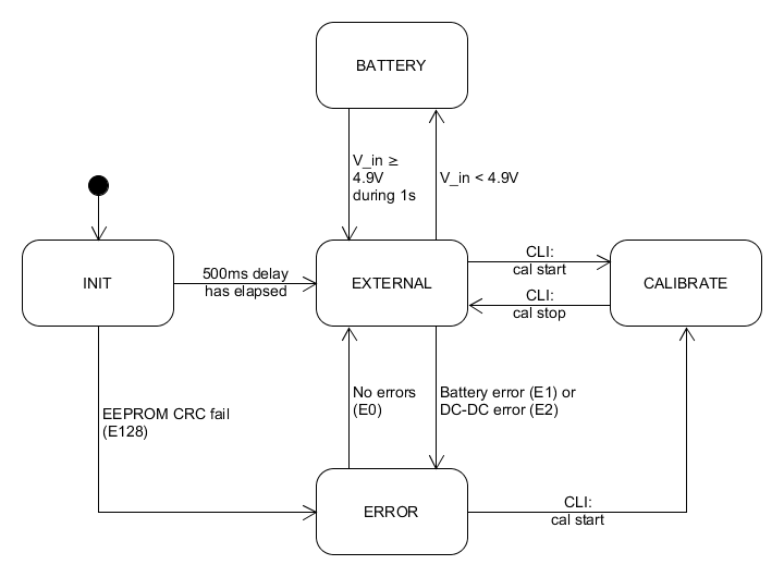
Upon startup the UPS reads the calibration data from EEPROM, verifies the CRC checksum and enters the INIT state where it waits for some time for the analog to digital converter (ADC) readings to stabilize. Once the initial delay has elapsed, the device transitions to the EXTERNAL state where it stays during normal operation.
is used for switching between the EXTERNAL and BATTERY states. Battery power is selected as soon as drops below 4.9 V. The external power is restored once the stays stable above 4.9 V for the duration of 1 second.
The UPS constantly measures and , calculates the battery charging state and reports an error condition if one of these voltages fall below a predetermined threshold. Whereas the following error conditions may occur:
- Battery error (error code 1): this error is registered whenever the battery voltage falls below 2.4 V. This error condition is reset if the battery voltage returns to normal, e.g. after reconnection the battery cutoff jumper.
- DC-DC converter error (error code 2): this error is registered whenever the DC-DC converter output voltage falls below 4.9 V. This error condition is reset once the DC-DC converter output voltage returns to normal.
- CRC error (error code 128): a failed CRC check during the INIT state. This error condition is reset upon reboot.
The ERROR state can only be entered from the INIT or the EXTERNAL states. If an error condition occurs during the BATTERY or the CALIBRATE state, the error code will be saved and the ERROR state will be entered as soon as the UPS is back to the EXTERNAL state.
Error codes are only cleared after the error event has been logged by the Raspberry Pi, this ensures that intermittent errors are always captured within the system log.
If more than one error occurs simultaneously, the resulting error code will be equal to the sum of the individual error codes.
The CALIBRATE state can be manually enabled by the user. In this state, the UPS enables external power and disables battery charging. Entering this state is required prior to calibrating the readings of , and . The CALIBRATE state is only accessible from within the EXTERNAL and ERROR states.
Battery Charger
The battery charger simplified version of the design described in the following article: https://www.microfarad.de/li-charger/.
The constant current constant voltage (CC-CV) charging logic is implemented in software, whereas the Arduino controls the gate of a P-channel MOSFET via pulse width modulation (PWM) in order to regulate the battery voltage and current.
The real-time battery voltage and current are derived as follows:
- (directly measured by the ADC)

Where is the external power supply voltage,  is the voltage drop of the Schottky diode connected in series with the battery (typically around 150 mV),
  is the value of the shunt resistor connected in series as well, and
  is the PWM duty cycle (ranging between 0 and 255). For more details, please refer to the circuit diagram.
The following figure shows the state machine of the battery charger.
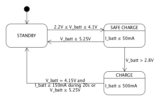
Charging begins when is within the acceptable range of 2.2 V to 4.1 V. Note that due to the presence of a battery protection circuit, the charger may see a voltage which is lower than the minimum limit for the Li-Ion chemistry (typically 2.5 V). Thus, the very low value of 2.2 V has been chosen.
If below 2.8 V, charging will be performed with a reduced charging current until the 2.8 V threshold is reached. Otherwise charging will take place at the preset current.
Once the reaches a maximum of 4.15 V,  is gradually reduced as to keep a constant voltage. Charging is terminated when stays below 150 mA for a duration of 20 seconds. Please note that, in order to compensate for measurement inaccuracy, the firmware source code defines a higher value for the end-of-charge current. Also note the reduced maximum voltage of 4.15 V against the typical 4.20 V for a Li-Ion cell has the aim of extending the battery service life.
The charging will be immediately terminated if suddenly rises above 5.25 V. This may happen if the battery becomes disconnected during charging.
Hardware
The following sections describe the hardware design of the UPS device.
Mechanical Design
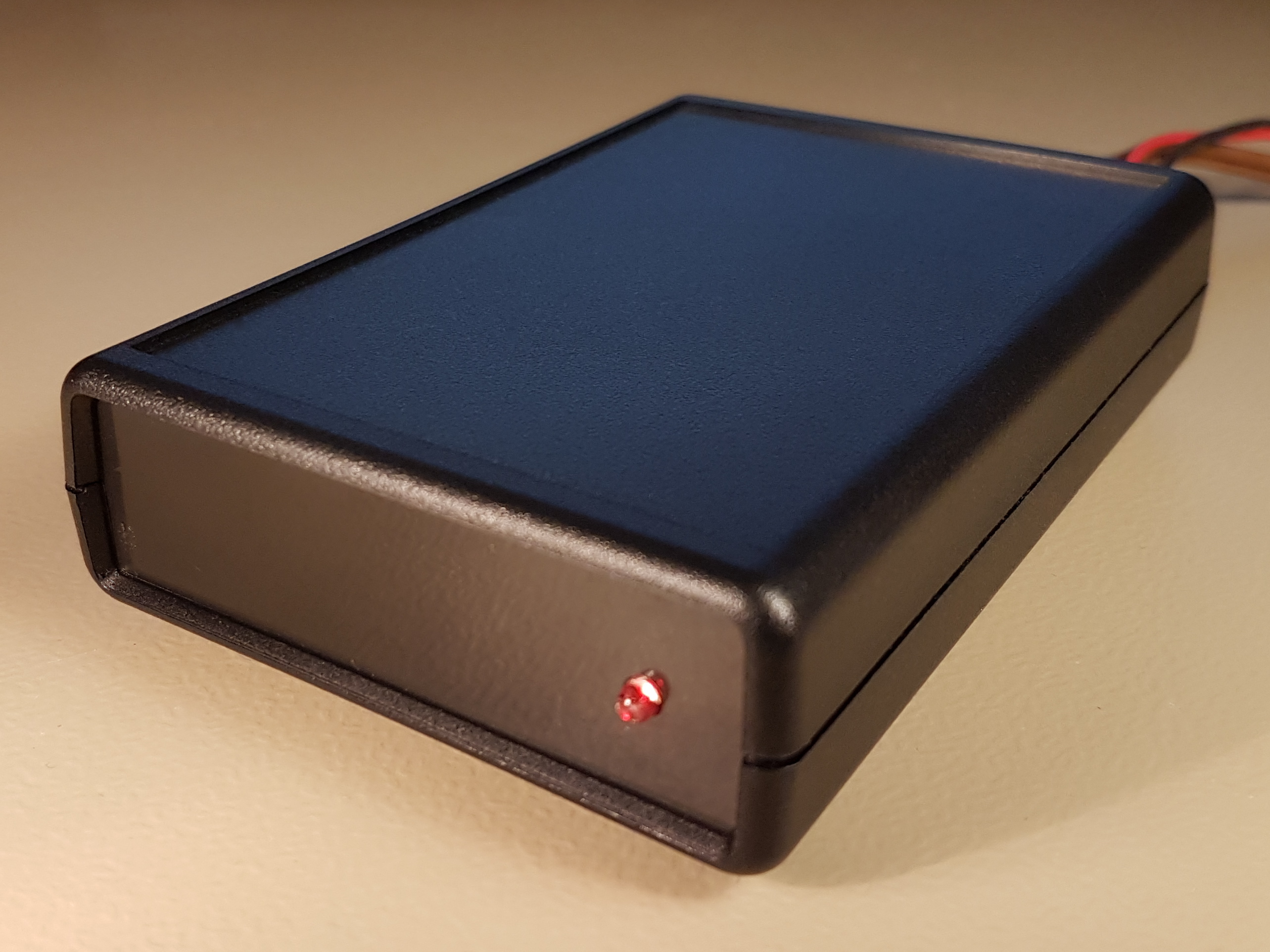
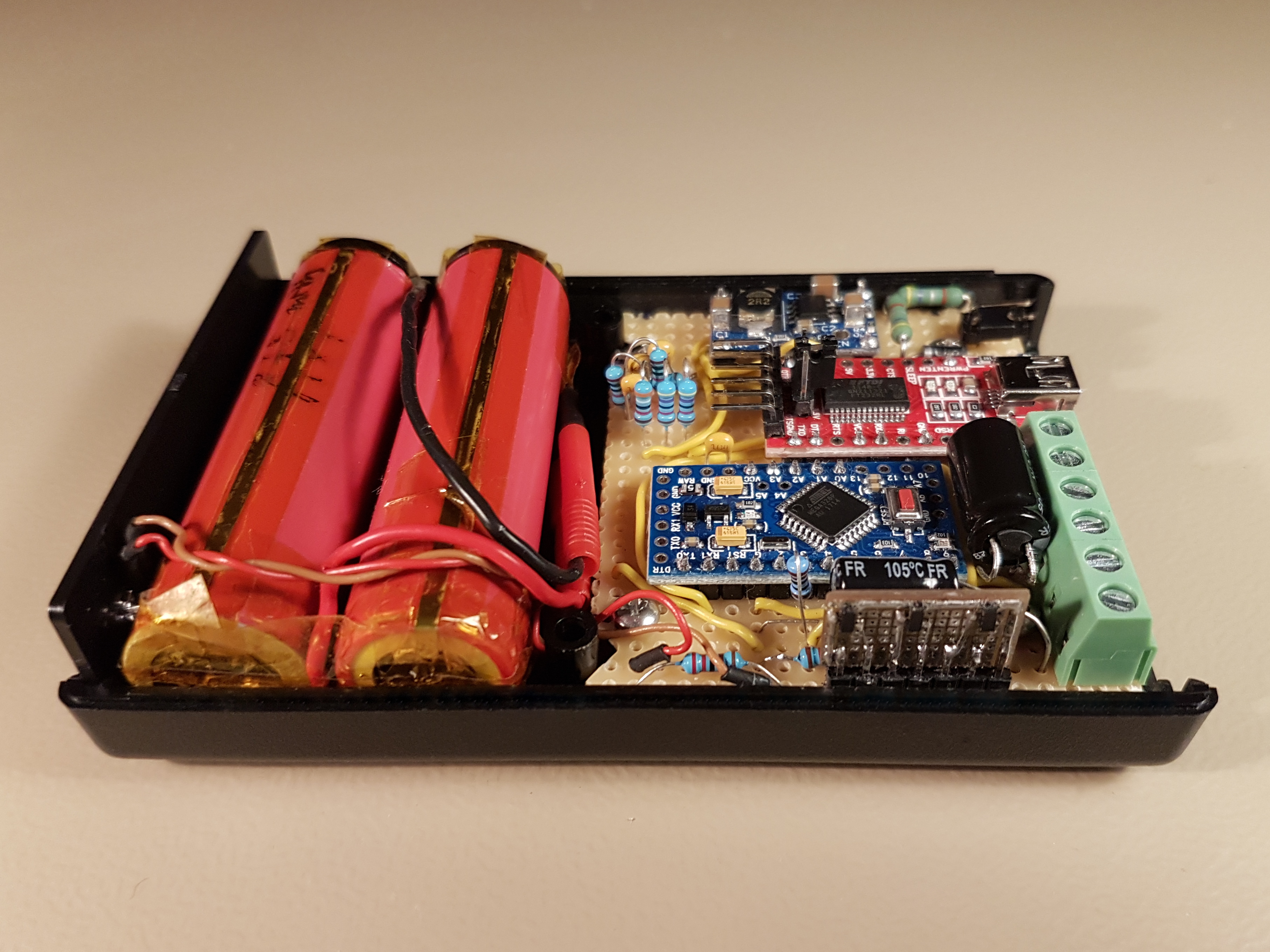
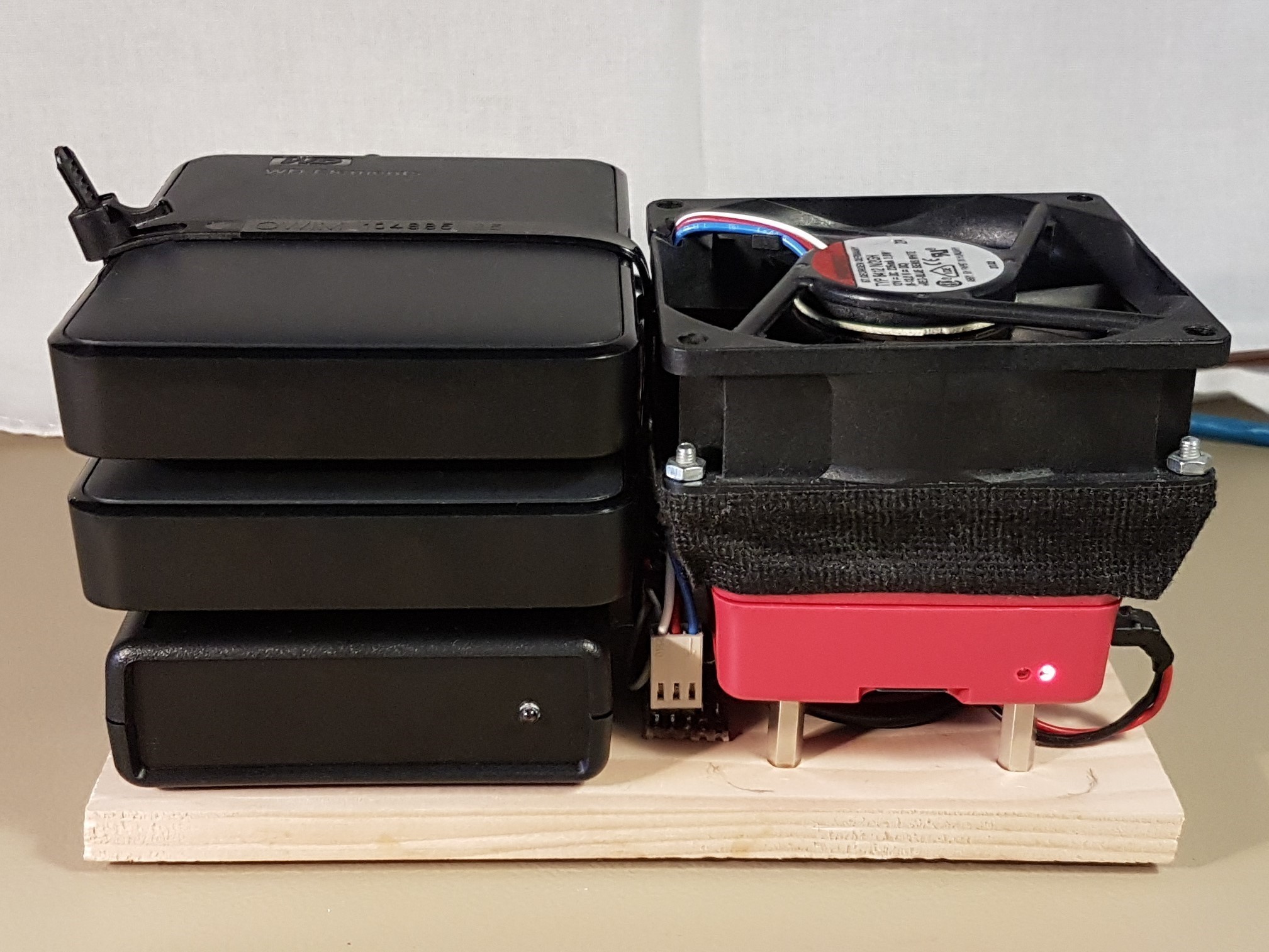
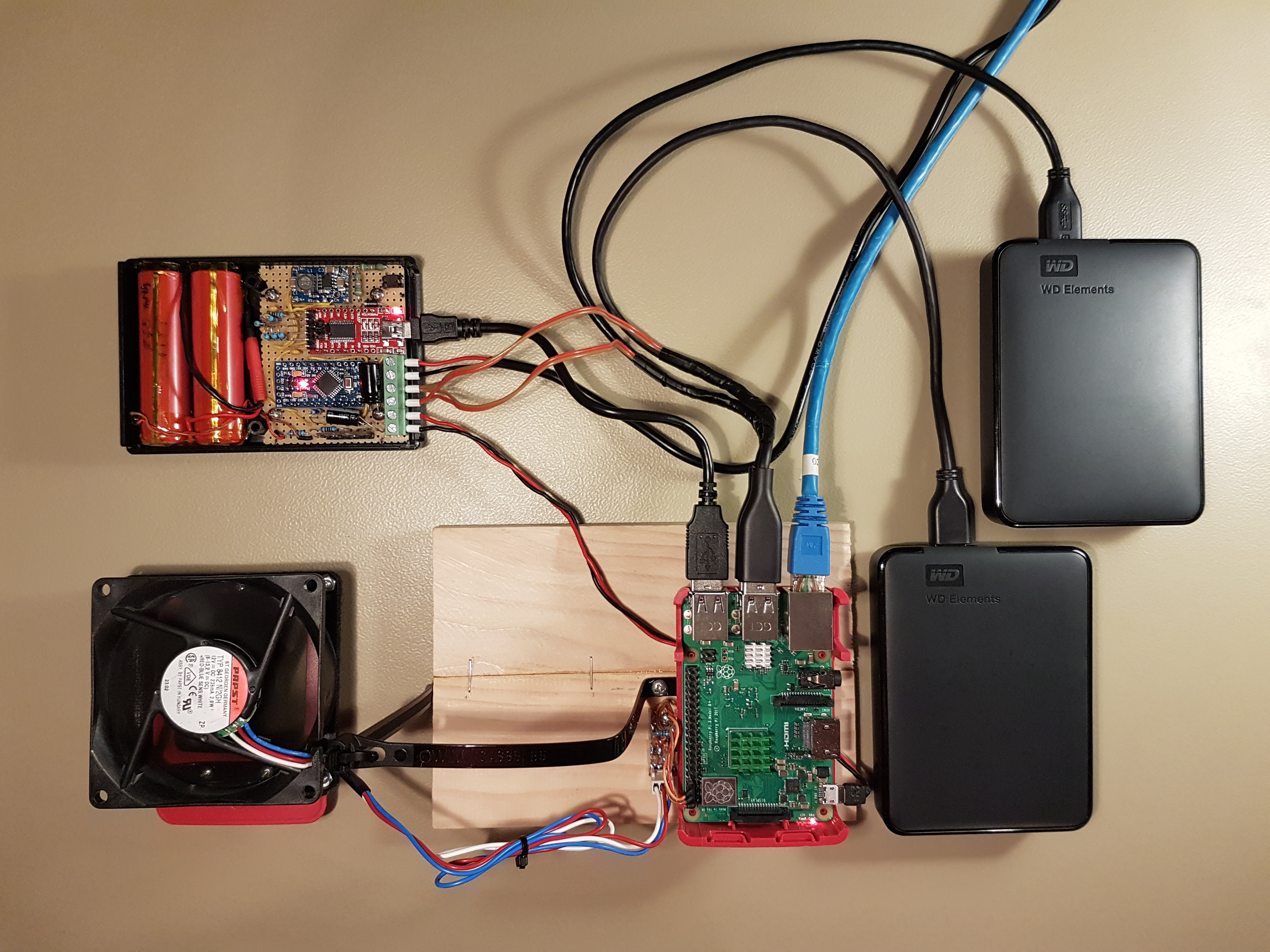
The UPS has been designed around an off-the-shelf plastic enclosure of type “RND 455-00889” measuring 111,3 x 75 x 25,2 mm. As shown in the picture below, this enclosure turns out to be a perfect fit for a pair of 18650 Li-Ion cells and a circuit board. Further, the footprint of this enclosure closely matches the footprint of a standard 2.5 inch USB hard drive; this gives us the convenience of being able to stack a USB hard drive on top of the UPS.
The above picture shows the following main components:
- Two 18650 Li-Ion battery cells: silicone cables (red and black) an 2 mm gold connectors (red plastic thing inline with the cables) has been used for connecting the battery with the main circuit board. The connector enables the battery to be hot-swapped without having to power down the Raspberry Pi. Temperature resistant Kapton tape has been used to hold the battery pack together and isolate its terminals.
- Two battery protection circuits: the two black protruding devices on top of the battery cells, each connected to the positive pole with a long metal strip that is isolated using Kapton tape
- DC-DC converter: the smaller blue device on top of the circuit board
- USB to serial converter: the red device on the circuit board
- Arduino Pro Mini: the larger blue device on the circuit board
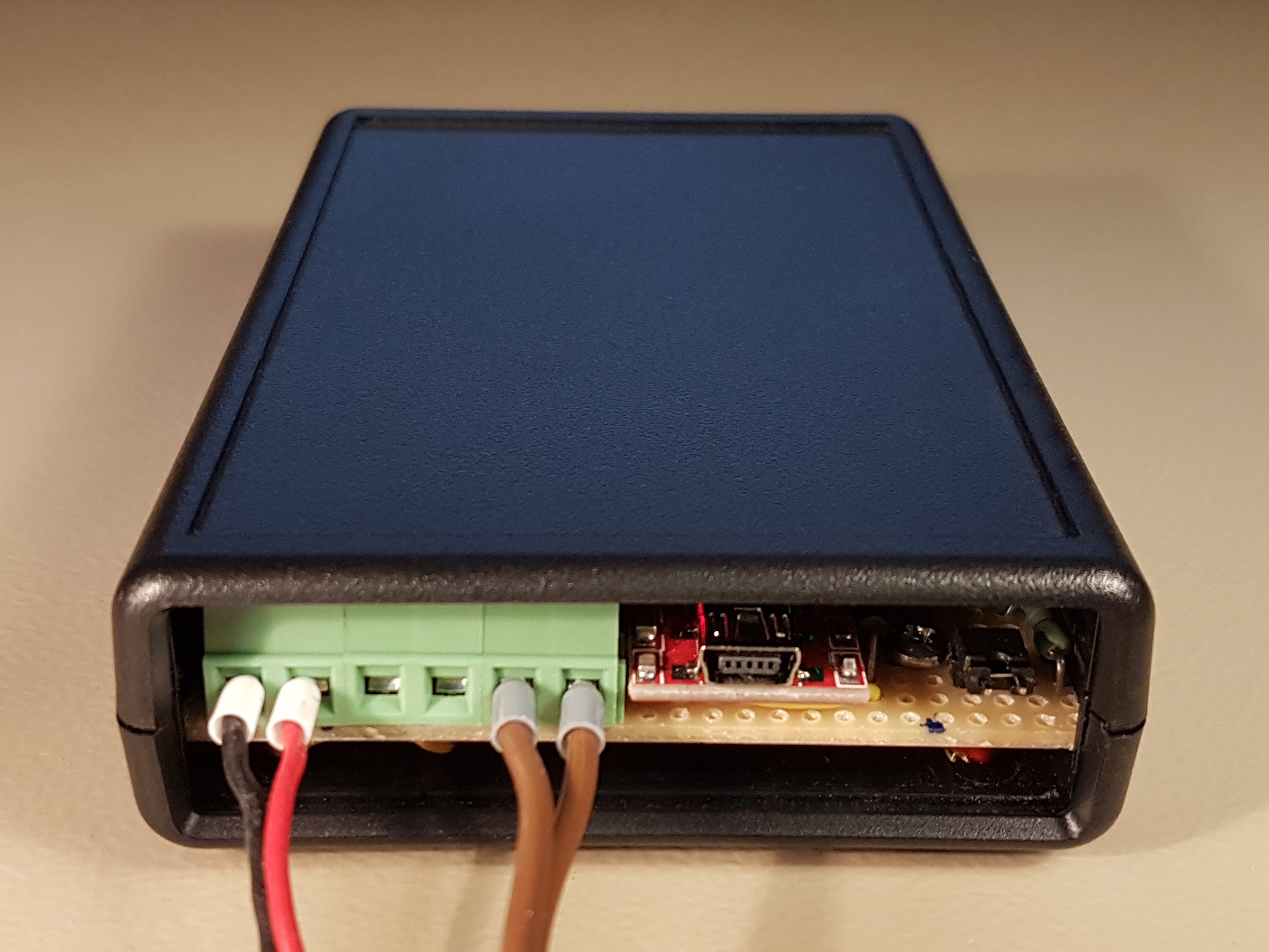
Further, the following elements have been lined-up towards the back of the enclosure in order to make them accessible by the user (on the right side of the above picture from top to bottom):
- Battery disconnect jumper: the user can remove this jumper to completely power off the device (after disconnecting external power).
- Mini USB port of the USB to serial converter: to be connected with one of Raspberry Pi’s USB ports
- Screw terminal block: for external power supply, hard drive and Raspberry Pi power lines
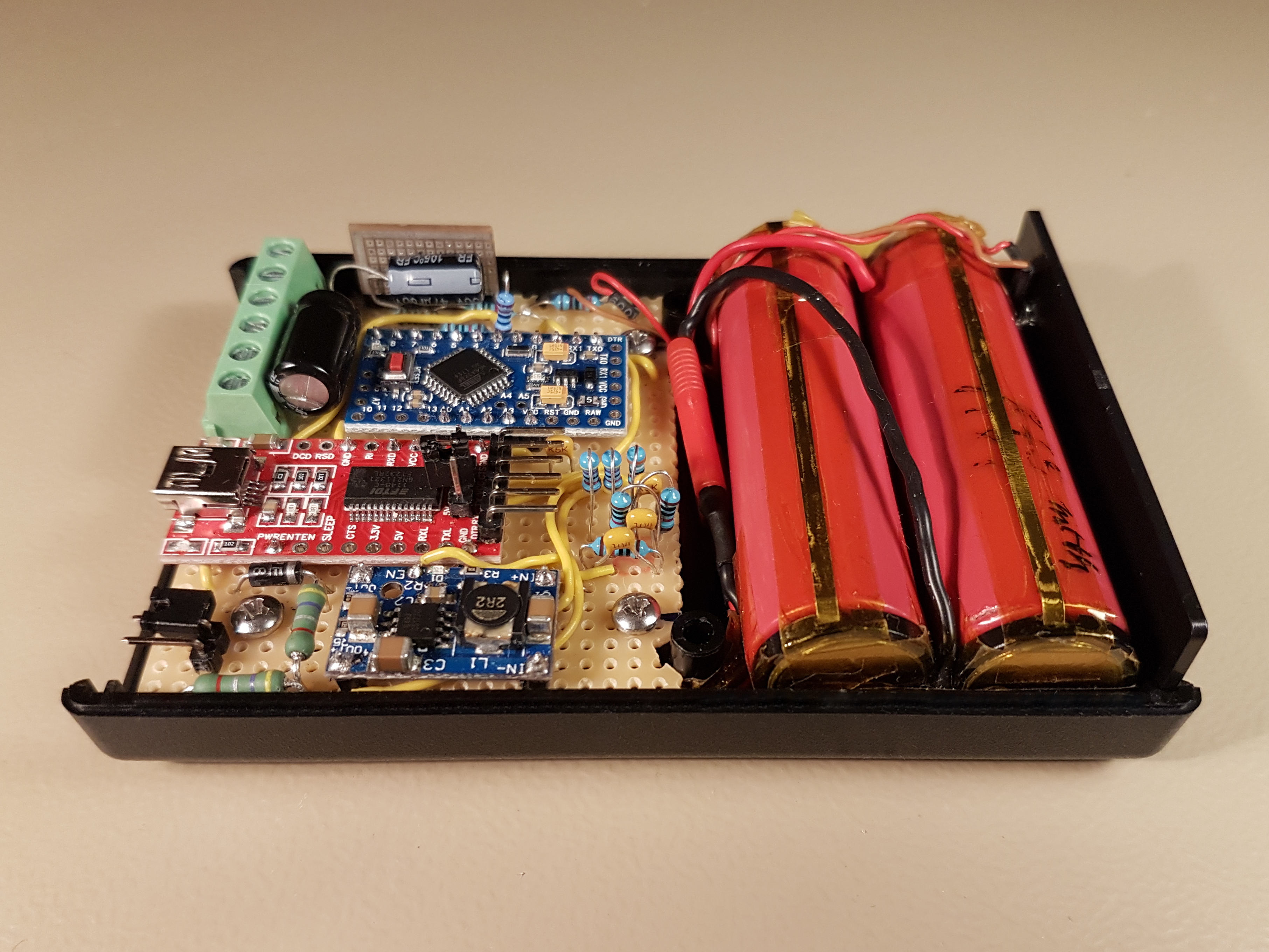
The following pictures show the UPS device from different perspectives (click to enlarge).
DC-DC Converter
The off-the-shelf DC-DC converter module shown in the picture below has been used for converting the Li-Ion battery voltage to the 5 V required to power the Raspberry Pi and its peripherals.
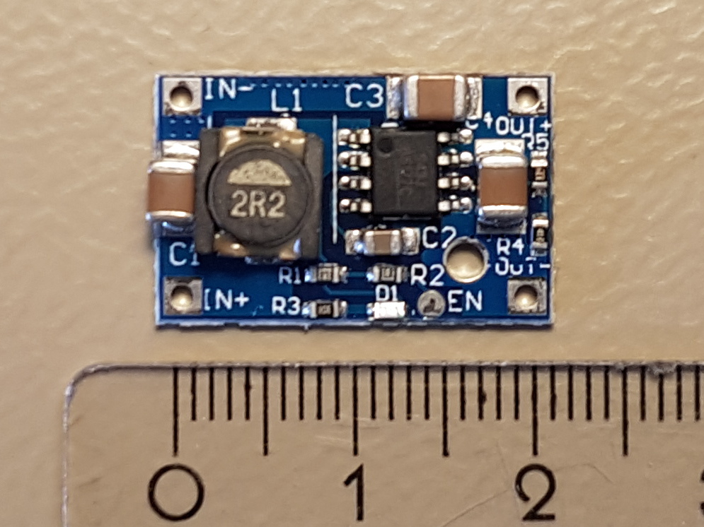
This device is based on the G5177 IC and can handle up to 3 A of output current.
The G5177 IC has been purpose built for boosting single cell Li-Ion battery voltage and has the perfect characteristics for the UPS application. Following is the datatsheet of this IC:
Following is the summary of its most relevant characteristics:
- It can easily handle the maximum 2.5 A required by the Raspberry Pi and attached USB hard drives.
- It has a very low quiescent current of less than 100 µA. Thus, it can stay connected to the battery at all times without causing a any significant discharge.
- It outputs a stable 5.3 V for a wide range of input voltages, which makes it ideal for powering the Raspberry Pi without activating the low battery warning.
- It has a pretty good efficiency.
Battery Protection Circuit
It is imperative to use a battery protection circuit for the Li-Ion battery pack in order to avoid accidental overcharge or over-discharge conditions which might result in catastrophic failure, violent explosion and fire.
Battery protection boards are readily available and come in different shapes and sizes. The particular device that has been used for this project is shown in the picture below.
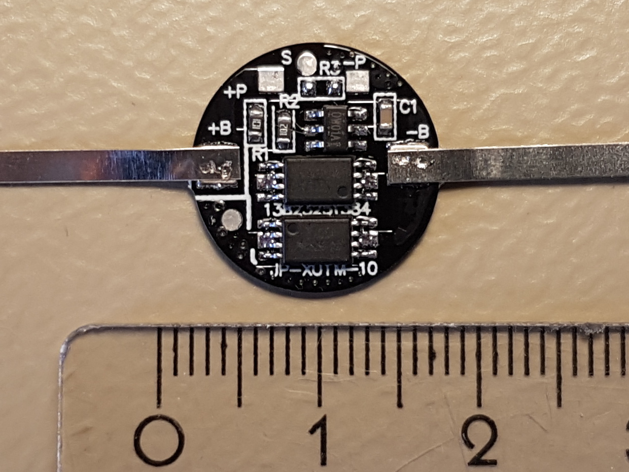
This device is designed for protecting a single 18650 cell and is rated for handling up to 5 A of current.
Two of these modules have been used in the UPS implementation, one for each of the Li-Ion cells, resulting in a total current capacity of 10 A which is plenty enough for this application.
The battery protection circuit connects in series with the negative terminal of the Li-Ion cell. It constantly measures battery voltage and current and automatically disconnects the negative terminal if one of the parameters goes out of bounds.
The device has the following 3 terminals as shown in the above picture:
- +B/+P: connects to the battery’s and load’s positive terminals
- -B: connects to the battery’s negative terminal
- -P: connects to the load’s negative terminal
Circuit Diagram
Following is the circuit diagram of the UPS device. The main sub-systems of the UPS device are described within the sections below.
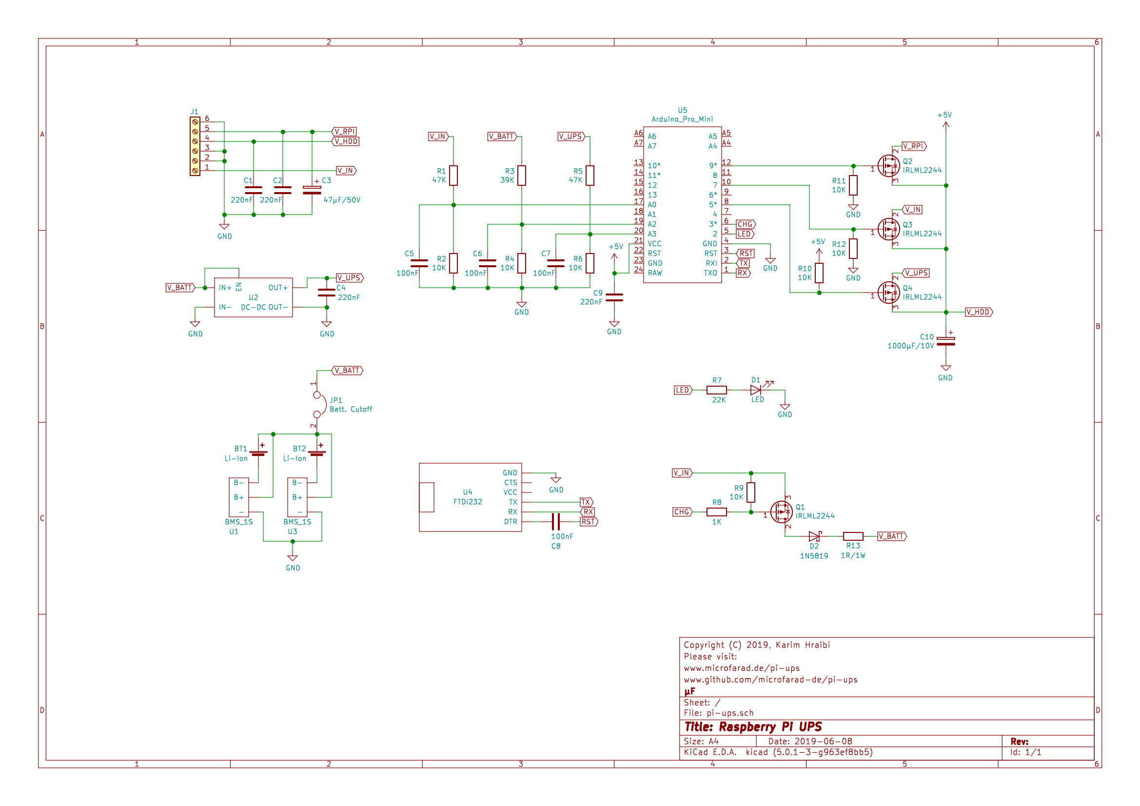
The following sections describe the different UPS sub-systems in more detail.
Microcontroller
The central processing unit of the UPS consists of an Arduino Pro Mini compatible board U5 featuring a 16 MHz ATmega328P microcontroller.
The Arduino measures the voltages , and on its analog pins A0, A2 and A3. Three voltage dividers built around R1 through R6 are used for lowering the measured voltages to fit within the range of 0 to 1.1 V expected by the analog to digital converter (ADC) inputs. Capacitors C5, C6 and C7 are there to provide smoother ADC readings by reducing high frequency noise on the inputs of the ADC.
The Arduino drives the gates of the power switch MOSFETS Q2, Q3 and Q4 using digital pins 5, 7 and 9. The battery charger circuit is driven by the PWM enabled digital pin 3. The LED status indicator is connected to digital pin 2.
USB to Serial Converter
A FTDI FT232 USB to serial converter U4 serves as an interface between the Raspberry Pi and Arduino. An Arduino Nano with an on board USB to Serial converter could have been used as well, however it is important to choose a version featuring the FTDI chipset as it does not require any additional drivers on most of the current operating systems.
The Tx and Rx pins of the USB to serial converter are connected to their respective counterparts on the Arduino. The DTR pin is connected to the Arduino’s reset pin via a 100 nF capacitor C8 to ensure that the Arduino is being properly reset prior to firmware upload.
Battery
The battery consists of two 18650 Lithium-Ion cells BT1 and BT2. Each of the cells is connected through its dedicated battery protection board (U1 and U3).
A jumper JP1 is used for disconnecting the battery’s positive terminal from the rest of the circuit. The user can completely shutdown the UPS device by disconnecting the external power supply and pulling this jumper.
DC-DC Converter
The DC-DC converter module U2 is used for boosting the Li-Ion battery voltage ranging from 2.5 V to 4.2 V to the 5 V required for powering the Raspberry Pi and its hard drives.
This particular model (based on the G5177 IC) draws a very low quiescent current of less than 100 µA when idling. Thus, it can stay powered on all the time without waisting any significant amount of energy. Keeping the DC-DC converter on all the time is required for minimising the voltage drop period during the transition from external to battery power.
Power Switch
The heart of the UPS is the power switch built around the IRLML2244 P-Channel MOSFETs Q2, Q3 and Q4. MOSFETs have been chosen due to their very low drain-source on-resistance  , which ensures that the external power supply voltage reaches the Raspberry Pi without any significant drop. The drain current
  of these MOSFETs is rated at 4.3 A which is more than enough for this application.
Q3 is responsible for switching the external power supply voltage . It has a pull-down resistor R12 connected to its gate to ensure that the MOSFET is on by default if there is no signal coming from the Arduino. This MOSFET is normally powered in reverse, whereas the current flows from the drain towards the source which is connected to the +5 V power rail.
Q4 is responsible for switching the DC-DC converter output voltage . It has a pull-up resistor R10 connected to its gate ensure that the MOSFET is off by default if there is no signal coming from the Arduino. This MOSFET is normally powered in reverse as well and has its source pin connected to the +5 V power rail.
Q2 is responsible for resetting the Arduino following a system shutdown. This MOSFET has a pull-down resistor R11 connected to its gate. It stays on most of time and can be turned off by the Arduino for a short while if the Raspberry Pi needs to be restarted after a system shutdown. In order to reduce the drain current and the resulting voltage drop, only the Raspberry Pi is being powered through this MOSFET while the hard drives are directly fed from the +5 V power rail.
If there are no signals present on the Arduino’s digital output pins, the power switch is configured such that external power is connected to the Raspberry Pi by default. The UPS is switched to battery power when the Arduino turns Q3 off and Q4 on by applying high and low logic levels on their respective gates.
In the seldom event where external power is lost while the Arduino is not properly working, the inherent diode inside the MOSFET Q4 ensures that would still reach the Raspberry Pi, though reduced by the amount of the diode voltage drop. The same applies for the case when the UPS is stuck in the battery power state while external power is present; the inherent diode of Q3 will conduct the external power. These fail safe modes have however their limitation because of the limited current capacity of the MOSFET inherent diodes. Though it should be enough for bridging the short gap during power switching between external and battery power.
Battery Charger
The battery charger is of a simple PWM design built around an IRLML2244 MOSFET Q1, similar to the Lithium-Ion battery charger described in this article.
The shunt resistor R13 is required for measuring the charging current and limiting the inrush current during the PWM on phase. The Schottky diode D2 prevents the battery power from being fed back into the external power supply through the inherent diode of the MOSFET.
Pull-up resistor R9 ensures that the MOSFET does not spontaneously turn on during the absence of a gate signal.
The gate resistor R8 is there to prevent very high current peaks to flow through the MOSFET’s gate capacitance and reduce the resulting electro-magnetic interference (EMI).
Filter Capacitors
In an effort to reduce the power supply ripple due to the PWM switching of the battery charger, the noise of the DC-DC converter and Arduino’s 16 MHz resonator. After trial and error measuring the power supply ripple using an oscilloscope the following filter capacitors have been added:
- 220 nF multilayer ceramic capacitors C1, C2, C4 and C9 have been installed across the Raspberry Pi and hard drive power outputs, DC-DC converter output and the Arduino’s VCC pin.
- 1000 µF low ESR electrolytic capacitor C10 has been installed across the +5 V power rail.
- 47 µF low ESR electrolytic capacitor C3 has been installed across the Raspberry Pi power output.
Note that one or more inductors could have been used to further reduce the EMI and power supply ripple, however this idea has been abandoned due the the lack of PCB space.
PCB Layout
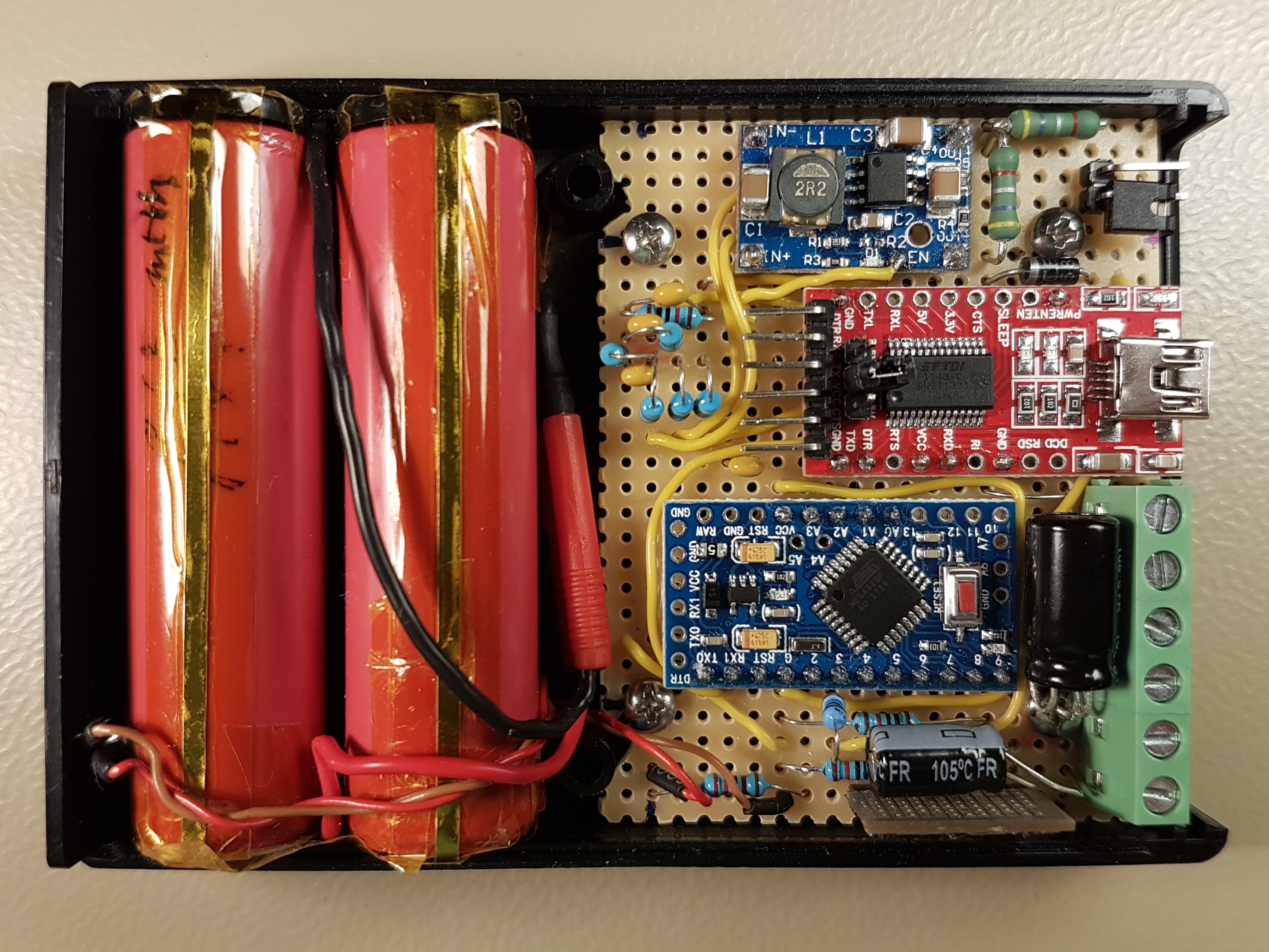
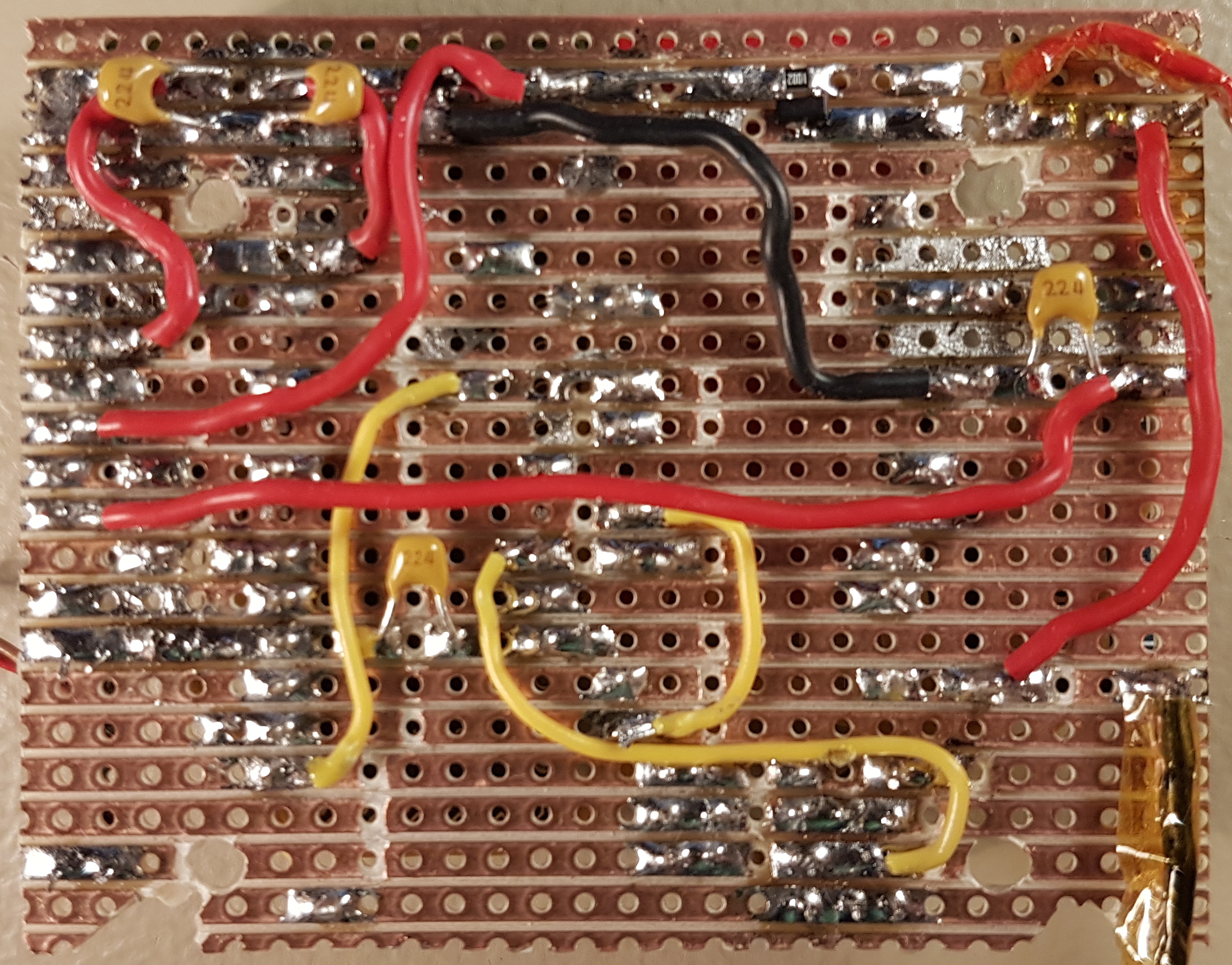
A combination of through-hole and SMD components have been populated on a stripboard PCB. The pictures below show the top and bottom sides of the main circuit board (click to enlarge).
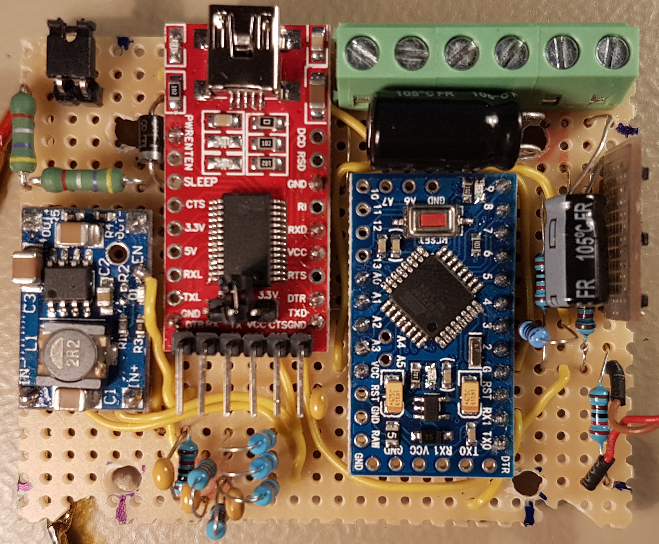
In the top layout picture, one can see the the following major components and their locations:
- DC-DC converter: smaller blue PCB
- USB to serial converter: red PCB
- Arduino Pro Mini: larger blue PCB
- Power switch MOSFET daughter board: grey PCB mounted vertically on the right side carrying 3 black SMD components
- Battery disconnect jumper: top left corner
- Battery charger: two green resistors and a diode at the top left corner (two 0.47 Ω resistors in series instead of 1 Ω)
- ADC voltage dividers: blue vertical resistors below the USB to serial converter
- Screw terminal block: green part in the top right corner
The following parts can be seen in the bottom layout picture:
- 4 220nF filter capacitors
- Battery charger MOSFET and its gate pull-up resistor: two black SMD components towards the top right of the picture
The following table shows the designation of the screw terminal block pins. Whereas pin 1 is the leftmost pin on the picture above.
| Terminal | Purpose |
|---|---|
| 1 (left) | External power + |
| 2 | External power – |
| 3 | Hard drive power – |
| 4 | Hard drive power + |
| 5 | Raspberry Pi power + |
| 6 (right) | Raspberry Pi power – |
User Interface
The following sections describe the user interface of the Raspberry Pi (RPi) UPS. It consists of a LED indicator and a Command-Line Interface (CLI).
LED Indicator
The status of the UPS is displayed using one single LED indicator. The following table shows the LED blinking patterns and their respective meanings.
| Blinking Pattern | Meaning |
|---|---|
| Blink twice – Period: 5 s to 6 s – On duration: 100 ms | State: EXTERNAL– External power – UPS is ready – Python script is running on the RPi – Normal operation |
| Blink once – Period: 10 s – On duration: 100 ms | State: EXTERNAL– External power – UPS is ready – Python script is not running – No event logging – No safe shutdown |
| Always on | State: BATTERY– Battery power – 100 % capacity left |
| Blink once – Period: 1 s – On duration: 750 ms | State: BATTERY– Battery power – 75 % capacity left |
| Blink once – Period: 1 s – On duration: 500 ms | State: BATTERY– Battery power – 50 % capacity left |
| Blink once – Period: 1 s – On duration: 250 ms | State: BATTERY– Battery power – 25 % capacity left |
| Blink quickly – Period: 200 ms – On duration: 100 ms | State: BATTERY– Battery power – 0 % capacity left – RPi will shut down |
| Blink quickly – Period: 400 ms – On duration: 200 ms | State: ERROR– System error – Battery disabled |
| Blink quickly – Period: 100 ms – On duration: 50 ms | States: EXTERNAL BATTERY ERROR– Waiting for the RPi to shut down |
| Blink once – Period: 2 s – On duration: 500 ms | State: CALIBRATE– Calibration mode – Battery disabled |
Command-Line Interface
This UPS features a Command-Line Interface (CLI) that can be accessed via the Arduino’s serial port. The easiest way to connect to the CLI is to open the serial monitor of the Arduino IDE while connected to the charger. Please ensure that the Baud rate is set to 19200.
Once up and running, the UPS will display a welcome message on the serial monitor and show the current firmware version. At this point, the UPS is ready to accept one of the CLI commands listed in the table below.
Some of these CLI commands need to be provided with arguments. Thus, one needs to enter a the command followed by one or two arguments separated by a white space.
| Command | Description |
|---|---|
h | Help – shows the list of available commands |
stat | Prints a brief system status on a single line. This command is periodically sent by the RPi and the resulting output is written to the system log |
status | Prints a detailed multi-line system status. In addition to the brief status, the output contains the values of , , , and the charger’s PWM duty cycle. |
rom | Prints the calibration values stored in EEPROM. The output contains the voltage calibration constants as well as the values for and . |
halt [abort] | Initiates a system shutdown. As soon as the remaining battery capacity reaches 0 %, the RPi sends this command to tell the UPS that it is going to shutdown. The ups will then wait for 60 s an then disconnect the power from the RPi until external power is available. Sending halt abort will cancel the shutdown sequence. |
test [abort] | Activates the UPS test mode which emulates the loss of external power. The test mode is terminated by sending the test abort command. |
rshunt <mΩ> | Sets , the value of the shunt resistor R13. <mΩ> is the resistance value in milliohms. |
vdiode <mV> | Sets , the voltage drop of the Schottky diode D2. <mV> is the voltage drop value in millivolts. |
cal <start| stop| vin| vups| vbatt> [mv] | Performs voltage calibration. The voltage calibration mode is entered by calling cal start and exited by calling cal stop. is calibrated using cal vin <mv>. is calibrated using cal vups <mv>. is calibrated using cal vbatt <mv>.<mv> is the measured voltage level in millivolts. Please refer to the next section for more details about the calibration procedure. |
wd <enable|disable> [hours] | Enables or disables the RPi watchdog timer feature. If enabled, a power cycle will be initiated on the RPi if the stat command has not been received during a predetermined amount of hours.The watchdog is enabled using wd enable [hours] where the optional parameter [hours] is the watchdog timer duration in hours.The watchdog is disabled using wd disable.The watchdog settings are stored in EEPROM and can be displayed using the rom command as follows:watchdog = <state> (<hours>h)Where <state> is the watchdog activation state (0 = disabled, 1 = enabled, 2 = triggered). The triggered state tells that the watchdog timer has expired at least once since the rom command was last called. <hours> is the timer duration in hours. |
Calibration Procedure
Following is a tutorial on how to perform the calibration of the UPS using the CLI over the serial monitor.
The calibration parameters are stored into the Arduino’s electrically erasable programmable read-only Memory (EEPROM). A cyclic redundancy check (CRC) checksum is appended to the configuration parameters set and stored into EEPROM as well. All configuration parameters are validated and out-of-range values are automatically replaced with the corresponding fail-safe values.
Upon initial startup, the serial monitor will show the CRC error message. This is expected as the EEPROM still contains some invalid values. The error message will disappear after the calibration procedure has been completed.
Voltage Calibration
Please proceed as follows in order to calibrate the readings of , and :
- Connect the UPS to a good 5 V power supply, do not connect the battery yet.
- Connect the UPS to the Arduino serial monitor.
- Enter
cal start, the messageCalibration startshould appear on the serial monitor. - Connect a fully charged battery pack.
- Measure the voltage between pins 1 and 2 of the screw terminal block J1 using a digital multimeter.
- Enter
cal vin <voltage>, where<voltage>is the previously measured voltage value in millivolts (e.g. 5120). The messageV_in_cal = <value>should appear on the serial monitor, where<value>is the calibration constant to be stored in EEPROM. - Measure the voltage between the closed jumper JP1 and ground.
- Enter
cal vbatt <voltage>, where<voltage>is the previously measured voltage value in millivolts (e.g. 4125). The messageV_batt_cal = <value>should appear on the serial monitor. - Measure the voltage across the output pins of the DC-DC converter U2.
- Enter
cal vups <voltage>, where<voltage>is the previously measured voltage in millivolts (e.g 5309). The messageV_ups_cal = <value>should appear on the serial monitor. - Verify that the calibration values have been stored in EEPROM by calling the
romcommand. - Double-check that the correctly measured voltages now appear within the output of the
statuscommand. - Enter
cal stopto finish the voltage calibration procedure , the messageCalibration stopshould appear on the serial monitor.
Current Calibration
Please proceed as follows in order to calibrate the reading of the battery charging current :
- Connect an amperemeter that is set to the 10 A range across the pins of the battery disconnect jumper JP1.
- Connect the UPS to a good 5 V power supply, do not connect the battery yet.
- Connect the UPS to the Arduino serial monitor.
- Enter
rshunt 1400,R_shunt = 1400mΩshould appear on the serial monitor. - Enter
vdiode 180,V_diode = 180mVshould appear on the serial monitor. - Verify that the values have been stored in EEPROM by calling the
romcommand. - Connect the UPS to a battery pack that is discharged to about 3.5 V, the battery should begin to charge and a current reading will appear on the amperemeter.
- Wait for 30 seconds for the reading to stabilize.
- Check the value of
 in the output of the
 statuscommand:- If the displayed value of is lower than amperemeter reading, then go back to step 4 and reduce by 50 mΩ.
- If the displayed value of is higher than amperemeter reading, then go back to step 4 and increase by 50 mΩ.
- If the displayed value of
Keep repeating steps 4 and 9 until the displayed value matches the value measured by the amperemeter. should be approximately 500 mA during the constant current charging phase and shall be gradually reduced as soon as reaches 4.15 V.
With the current implementation, is not possible to calibrate the reading of to be correct for the whole range from 0 to 500 mA. Therefore it is critical to calibrate for an accurate reading at 500 mA in order to ensure that the charging current never exceeds this limit. It is ok to have inaccurate readings at for smaller values, whereas will tend to read too high at the low end of the range. For this reason, you will notice that the macro I_FULL within LiCharger.cpp is set to 200mA, whereas the intended end of charge current is about 150 mA.
Note that the configured value of may be larger than the real value of R13. This is due to the parasitic impedance of the components connected in series with the battery (wires, jumper, MOSFET, etc.).
Downloads
Among others, below you can find GitHub download links for the Arduino firmware source code and KiCad schematic source files. All of the source code is distributed under the GNU General Public License v3.0.
Please note that the current implementation uses the watchdog timer functionality which requires the customized Arduino bootloader found under the link below. Additionally, ensure that you use Arduino IDE version 1.8.19 to compile the firmware. For more details, please follow the installation instructions found within the README file on GitHub.
Hello, have you thought about transferring this UPS from Arduino to ESP32 so that it can be better integrated with home assistant?
Hi Lukasz, there is nothing speaking against running the UPS on an ESP32. Actually, ESP32 would be an overkill for such a relatively simple implementation, in terms of features and computing power. Please feel free to fork the Github repository and perform the necessary adaptations. Best regards, Karim
Is there something wacky about the irlml2244 MOSFETS’ in the schematic? They look backwards. Could it be the device in the KiCA / EasyEDA program?
Thanks!
73 Gary w8RGB
Hi Gary,
thanks for the feedback. Not really, the MOSFETs are backwards by design. As described in the ‘Power Switch’ section under the circuit diagram, the MOSFETs are aligned such that their body diode points in the direction of V_IN and V_UPS. This has two different purposes:
– Preventing current flowing backwards into the battery or the power supply
– The MOSFET body diodes ensure that the Raspberry stays powered during the transient period while switching to/from battery power.
I used Kicad for the circuit diagram and selected the right symbol for the IRLML2244.
Best Regards,
Karim DD2KH
Hi,
Thanks for the project it’s really nice. But one thing confuses me you have given a link to the G5177 datasheet and there it states “Guaranteed 1.8A Output Current at VOUT = 5V from 3.0V Input ” whereas you mentioned the IC will handle 3A. If I am not mistaken you are talking about “G5177C” instead of “G5177” Please note the extra “C”. Correct me if I am wrong.
Also, can you help me in altering the circuit to use the supercapacitor 10F 2.7V instead of a battery? I do not need backup power I need a graceful shutdown in case of a power surge. Also, batteries are not environment friendly. I want to avoid them.
Last but not least Would you please guide me to handle the output 5V 4A. I need 4A because I am using the nanopim4v2 SBC board which is power-hungry when all peripheral devices are attached.
Your help will much be appreciated.
Hi Rajiv, thanks for your comment. According to the datasheet, I_LIM “Peak Current Limit” can go up to 4.6 A, but the actual current rating depends on the circuit implementation, so it is 3A for the particular board that I used. Unfortunately my time is very limited, so I would be happy to answer any question regarding the current design, however it would be difficult for me to find the bandwidth for supporting any customisation work. Nevertheless, for a supercap you won’t need any of the lithium charging logic nor the circuit around Q1. Though I’m not sure if a supercap can power the RPi and HDDs for long enough to ensure a safe shutdown (you mentioned 4A). The actual DC-DC converter that I have been using is no longer available on Ebay, so you’re gonna have to search for a replacement part, so there is nothing against using a boost converter with a greater current rating. Regards, Karim.
Hello, great project. May you please tell me which external power source you are using (simple charger 220v to 5v and and around 3A?)
Thank you in advance for your response
Hi Inout, thanks. I use the “Aukru Micro USB 5V 3000mA” power supply which I bought on Amazon.de under the following link: https://www.amazon.de/gp/product/B01566WOAG/ref=ppx_yo_dt_b_search_asin_title?ie=UTF8&psc=1 . It is one of the few power supplies that delivers more than 5.3 V when Raspberry is connected. This is enough to overcome the voltage drop across the MOSFETs and prevents the Raspberry Pi from giving a low voltage warning (red power LED turning off). Best regards, Karim
This is great. I am trying to find a similar solution for a Carputer UPS and want to understand the following things.
1. I will be powering the UPS from micro usb charger connected to 12v DC socket. So 5V input.
2. I want the UPS to power the Carputer when the ignition and accessory is off – like a parking mode for the dashcams
3. I want to use LiFePO4 batteries instead of LiPo to make it safer.
What modifications do I need to do for point 3 above?
Hi Atri,
thanks for your feedback, it sound like a nice project you are doing. You can power the UPS from a micro USB charger, however please ensure that the charger can handle at least 3 Amperes as it needs to both power the Raspi and charge the battery at the same time. LiFePO4 batteries are usually charged up to 3.6V (4.2V for LiIon). Thus, you would need to reduce the voltage thresholds defined in LiCharger.cpp as follows:
#define V_MAX 3550000 // 3.55 V – Maximum allowed battery voltage per cell in µV
#define V_START_MAX 3500000 // 3.50 V – Start charging below this voltage per cell in µV
#define V_START_MIN 2000000 // 2.00 V – Start charging above this voltage per cell in µV (lower than V_MIN to overcome BMS shutdown)
#define V_SURGE 3650000 // 3.65 V – maximum allowed surge voltage threshold per cell in µV
#define V_SAFE 2500000 // 2.50 V – Charge with reduced current I_safe below this voltage per cell in µV
IMPORTANT: to avoid any explosion or fire, please use a dedicated off-the-shelf battery protection circuit designed for LiFePO4 batteries.
Best Regards,
Karim
This is exactly what I’m looking for. Honestly I’m a beginner with circuits, but I hope I can implement the same at home. Is this hard to modify your circuit with the followings:
– Operate with external 2 pin 18650 array? (up to 10 cells)
– Change both the input and output to USB-C?
– Connect somehow with the raspberry for central management?
Thanks a lot, this is awesome
Hi NextGeneration, thanks for the positive feedback. Trying to answer your questions:
– Yes, you can use as many 18650 cells in parallel as you wish, just please ensure that you use a battery protection circuit. Please note that your battery pack must be rated for at least 5 Amperes.
– Yes, it is surely possible to replace the screw terminals with USB-C or any connector you like, as long as it is rated for 3 Amperes or more.
– The current design actually connects to the Raspi via USB, please see description. Best regards, Karim.