Following is the tutorial for a DIY home server using a Raspberry Pi featuring a temperature controlled fan, UPS, incremental backup, photo stream, self-diagnostics and more…
The server described in this article is being used for hosting this website.
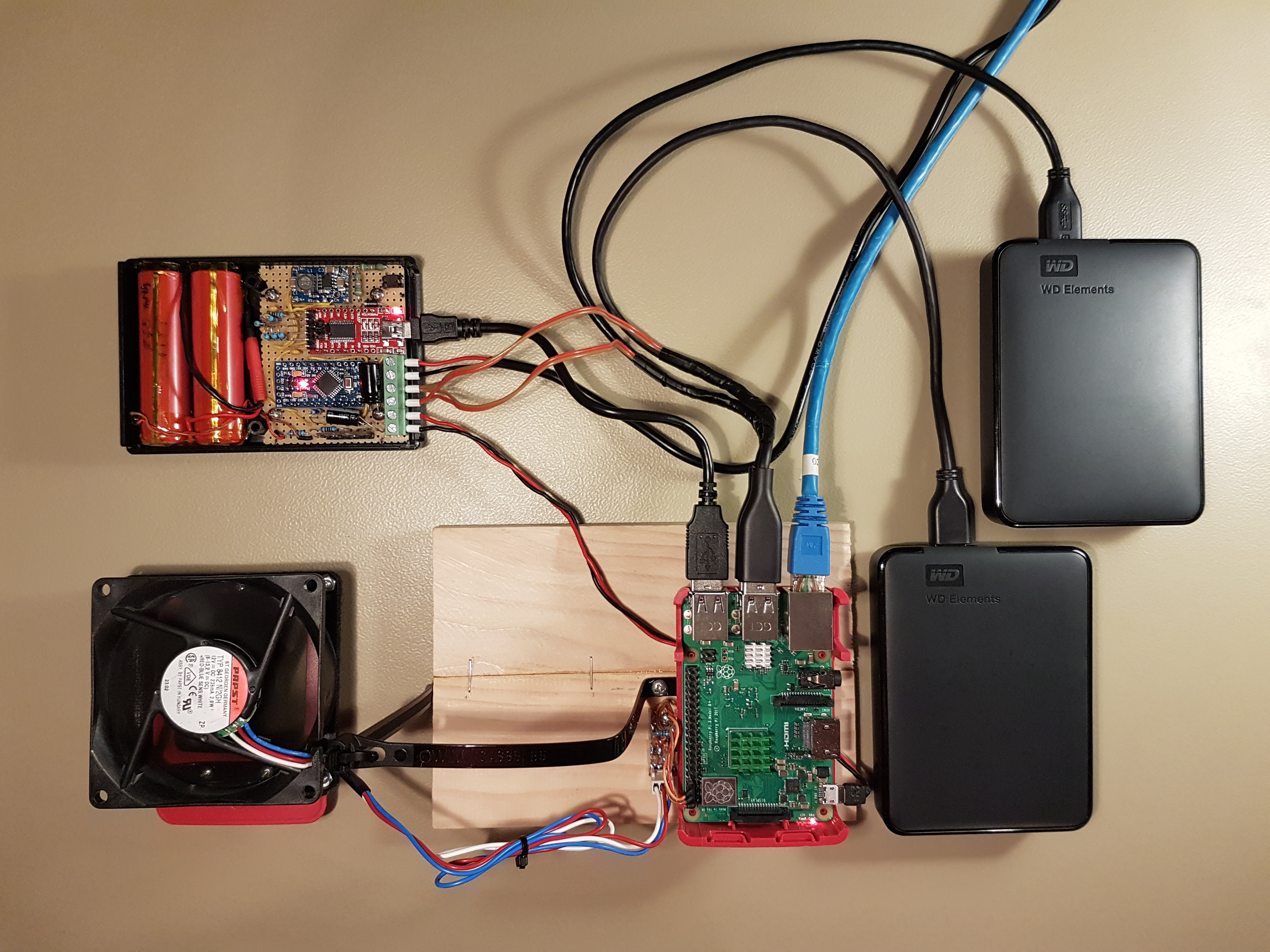
It consists of a Raspberry Pi 3 B+ connected to a pair of USB hard drives (HDDs), one main and one backup HDD, 4 Terabytes each. The oversized cooling fan mounted on top is controlled over the Raspberry Pi’s GPIO pin and keeps the CPU temperature at a constant 50 °C. An uninterruptible power supply (UPS) provides backup battery power and ensures a safe shutdown in the event of a total power loss.
The system is characterised by a low power consumption of about 6 Watts when idle. It is a very stable system and can run for months without rebooting.
Table of Contents
Hardware
The following hardware has been used for building the server:
- Raspberry Pi 3 B+ (ARMv8, 64 bit, 1.4 GHz, 1GB SDRAM)
- Raspberry Pi Enclosure: official Raspberry Pi
- SD card: SandDisk Ultra 32 GB microSDHC
- HDD: 2x Western Digital Elements WDBU6Y0040BBK-WESN 4 TB USB
- Cooling Fan: Papst 8412 N/2GH, 8 cm, 12 V DC, 235 mA
- UPS: DIY using Arduino (link)
- Heat sink kit for the Arduino
- Custom HDD power cables
- Power distribution cables
- Wooden base: measuring 16.5 x 11.6 cm
- Power Supply: Aukru Micro USB 5V 3000mA
The hardware setup is described in the following sections.
Mechanical Design
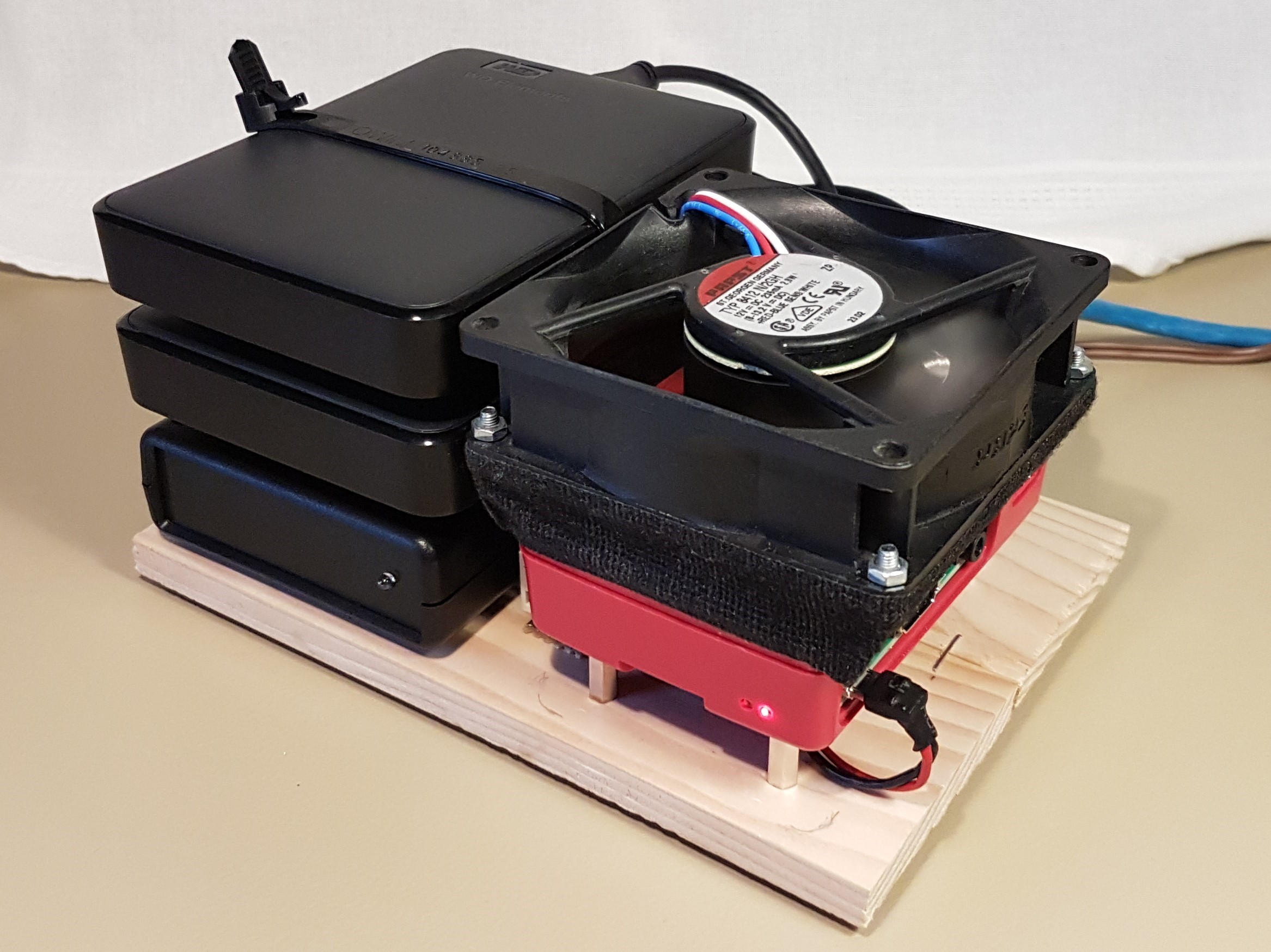
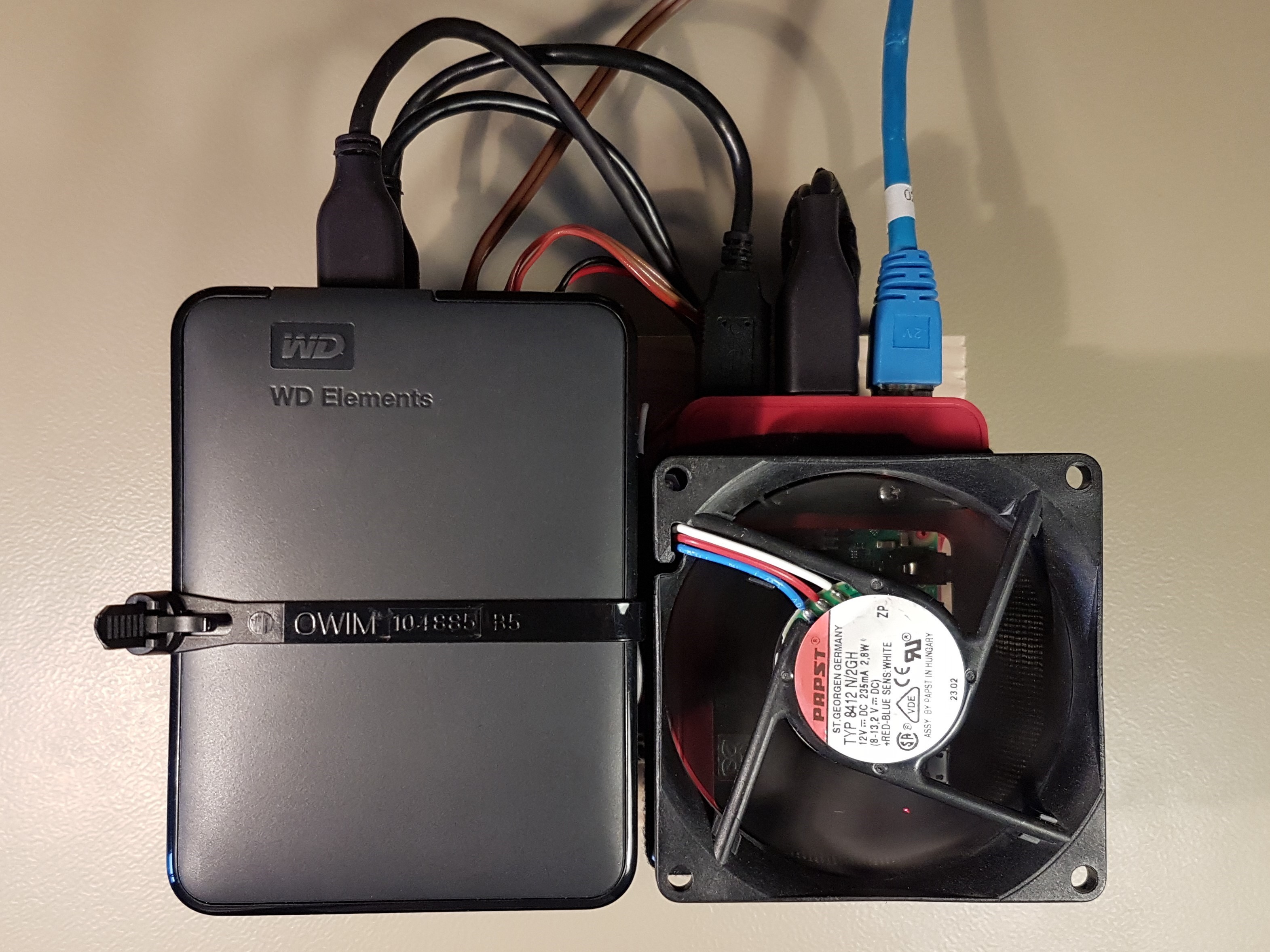
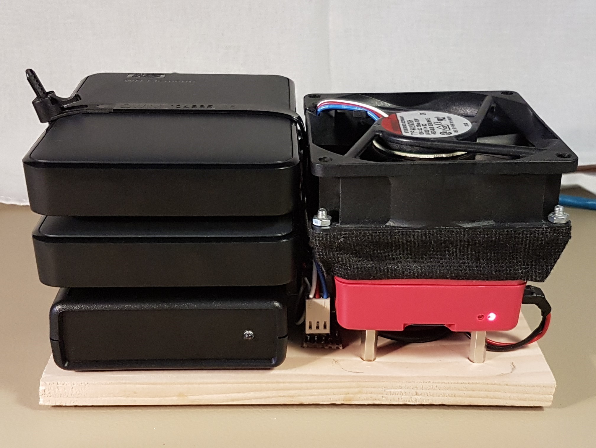
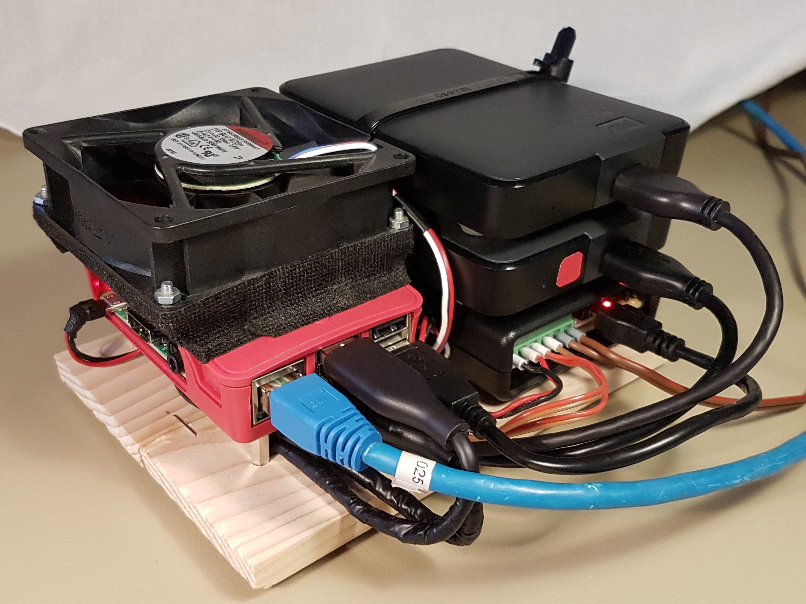
The complete hardware is mounted on a wooden base. The Raspberry Pi’s enclosure is attached to the base using 4 metal stand-offs. The UPS and both hard drives are stacked on top of each other and secured using a releasable cable tie. The ends of the cable tie are fastened to the wooden base using self-tapping screws.
Pieces of the same kind of cable tie, cut and with holes drilled in it is used to secure the cooling fan on top of the Pi’s enclosure using bolts, nuts and self-tapping screws. The enclosure itself is left open from the top and the sides in order to allow for the air to flow. A piece of automotive electrical tape seals the gap between the enclosure and the fan.
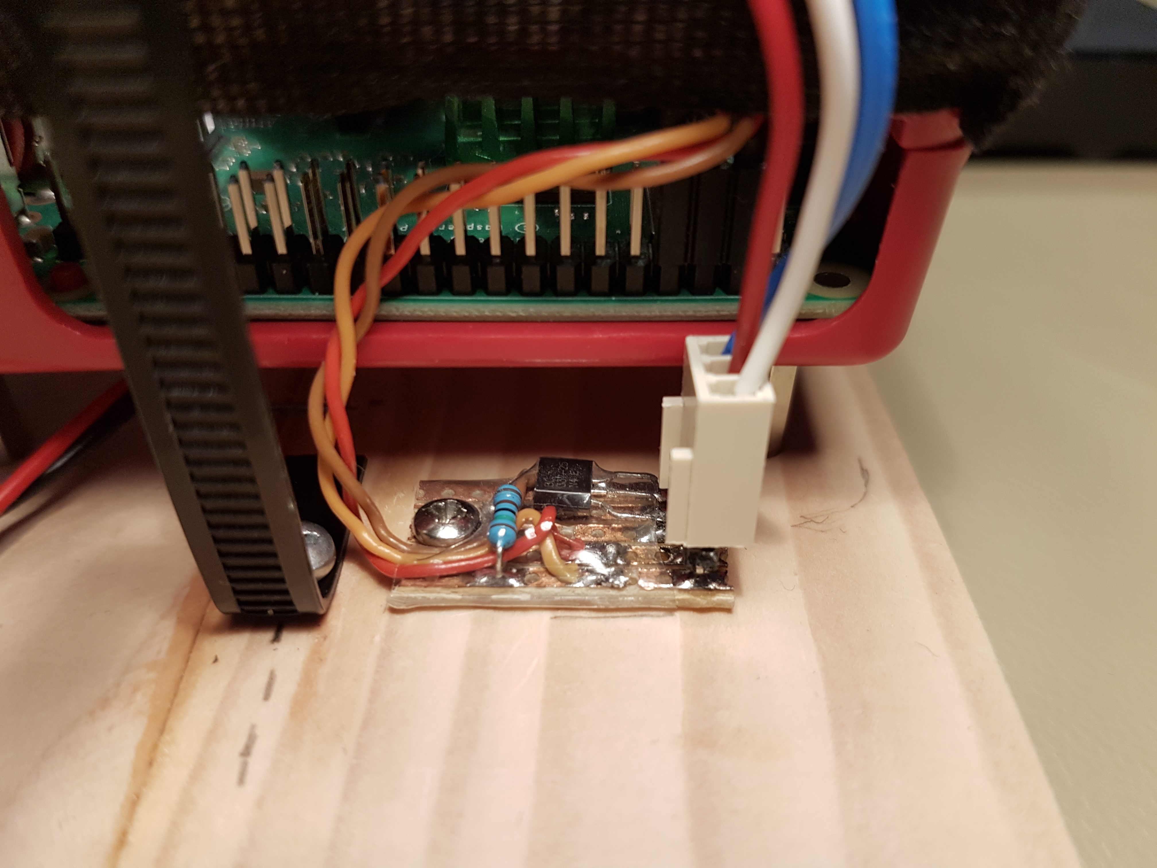
The space underneath the Raspberry Pi that has been created by the stand-offs is used for stowing excess cables.
A fan control circuit board is positioned near Pi’s GPIO header and is attached to the wooden base using a self-tapping screw.
The following pictures show the hardware setup from different perspectives.
Power Supply
A good quality USB power supply rated above 3 Amperes is required for powering the system. In order to prevent the Raspberry Pi’s low voltage warning LED from lighting and the resulting CPU clock reduction, the power supply must be able to sustain a high output voltage of at least 5.3 V at its maximum rated current.
It turned out to be quite a challenge to find a power supply that meets the above requirement, whereas the following model has proven to be suitable for this application: Aukru Micro USB 5V 3000mA (Amazon link).
The power is fed to the UPS device (link) which distributes it among the Raspberry Pi and HDDs.
Depending on the load, the power consumption of the system ranges between 6 and 13 Watts (excluding power adapter losses).
The Raspberry Pi has a limited capacity of powering loads through its built-in USB ports. Consequently, each of the hard drives is powered independently using its own custom made USB cable.
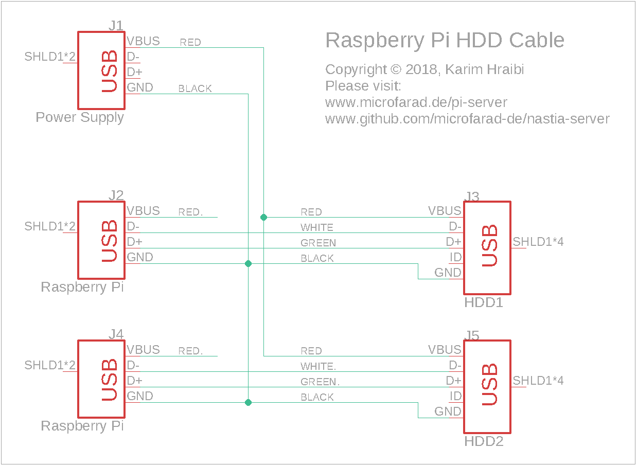
The following schematic shows the wiring of the custom USB cable used for powering the HDDs. The micro-USB cables bundled with the HDDs have been modified by cutting the red wire and connecting the HDD side of it to the positive lead of the power supply while leaving the Raspberry side of it disconnected. The negative power supply lead has been spliced into the black wire.
Cooling Fan
The Raspberry Pi requires active cooling in order to maintain its CPU clock frequency of 1.4 GHz. Without any active cooling, the CPU would quickly throttle down to 1.2 GHz as soon as it is subjected to any noticeable load. The Raspberry Pi is cooled by an oversized 12 Volt fan. The fan is powered by Pi’s 5 Volt power supply which is way below the its nominal voltage. The fan’s relatively large diameter enables it to provide adequate cooling despite the relatively low RPM due to the undervoltage. The advantage of such a setup is that it results in a virtually silent cooling system.
The fan is temperature controlled. Fan control is achieved via one of the Raspberry Pi’s GPIO pins. The GPIO pins on the Raspberry can only supply 3.3 Volts and their output current is way too low to power the fan. In order to solve this issue, the GPIO signal drives the base of a NPN transistor which in turn switches the 5 V power supply and can provide enough current for running the fan.
The figure below shows the pinout of the 40 pin GPIO header on the Raspberry Pi 3 and similar models (source: www.elektronik-kompendium.de/sites/raspberry-pi/1907101.htm).
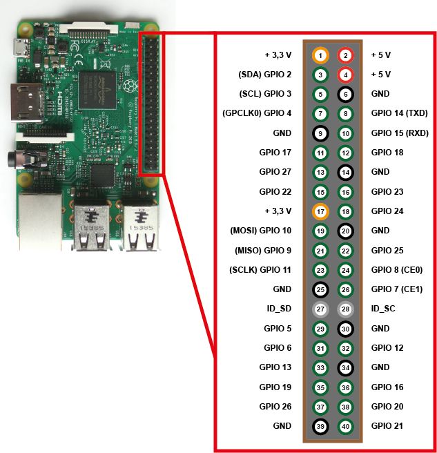
For the sake of convenience, GPIO pin GPIO 14 (pin 8) and the adjacent ground (pin 6) and 5 V (pin 4) pins are used for connecting the fan control circuit. Thus, one single 2.54 mm female pin header to connect to the three adjacent pins. Nevertheless, you may use any of the available GPIO and power pins for the same purpose.
The figure below shows the schematic of the fan control circuit.
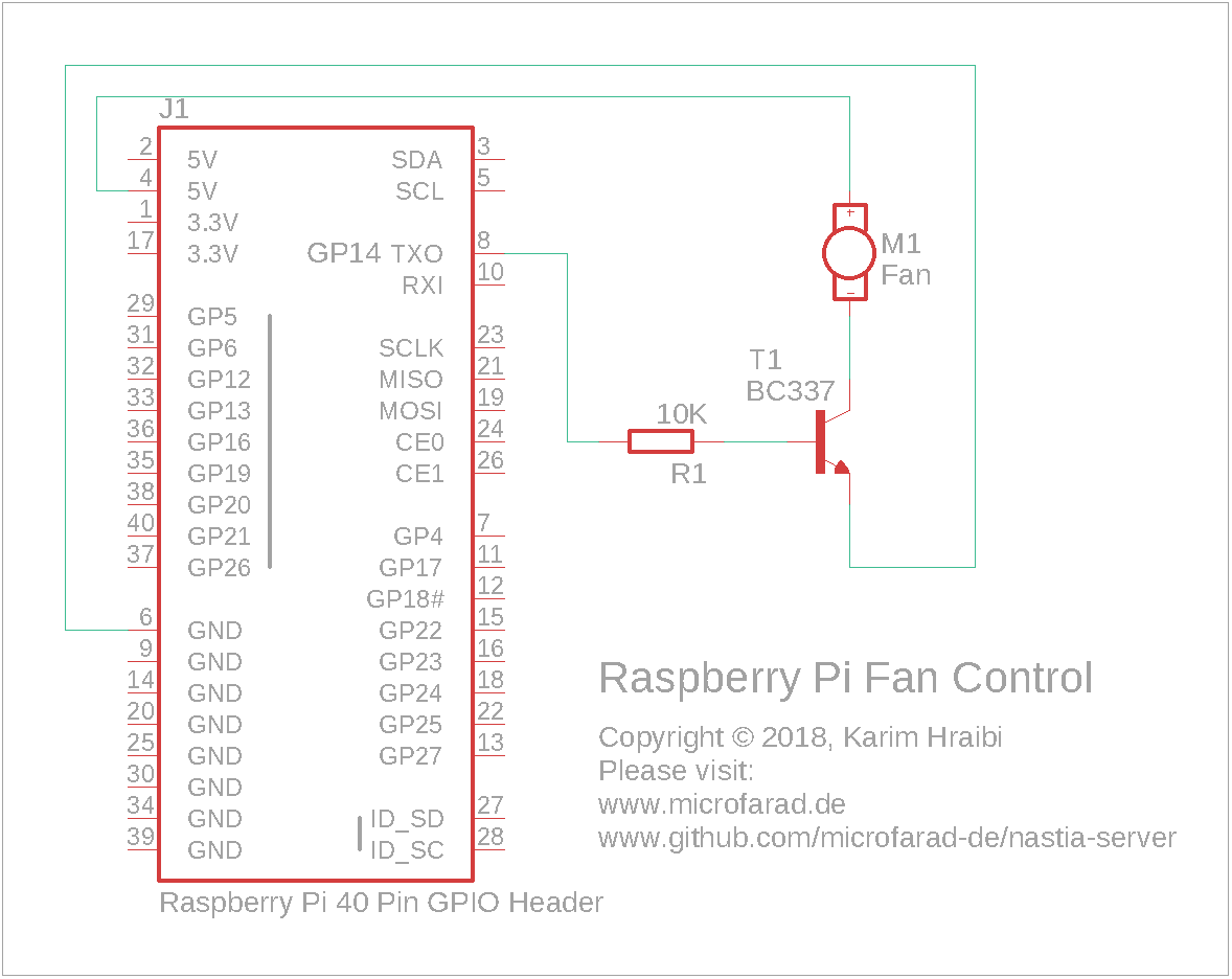
In the above schematic, pin GP14 (GPIO 14) drives the base of the BC337 NPN transistor T1 via a 10 KΩ current-limiting resistor R1. The transistor is configured in a common-emitter circuit, which means that the emitter (pin with the small arrow) is connected directly to the negative power supply, while the collector is connected to the negative terminal of the fan DC motor. The fan motor’s positive terminal is connected to the +5 V power supply.
The GPIO pin is controlled by the following shell script that can be configured to run as a Linux service. The below code is already integrated into the software package that can be downloaded further down below. A form of this code can be found under /opt/nastia-server/bin/fan.
#!/bin/bash
#
# Fan Control Over GPIO
#

THRESHOLD=50     # temparature threshold in degrees Celsius
INTERVAL=5       # temperature sampling interval in seconds
LOG="/home/pi/fan.log"  # Main log file
GPIO_PIN=14      # GPIO pin connected to the fan

# Print info message to log file
function infoLog {
  echo "$1" >> "$LOG"
}

infoLog "fan control service started"

# Initialize GPIO
if [[ ! -e "/sys/class/gpio/gpio$GPIO_PIN" ]]; then
  echo "$GPIO_PIN" > "/sys/class/gpio/export"
  if [[ $? -eq 0 ]]; then
    infoLog "initialized GPIO pin $GPIO_PIN"
  fi
fi

# Set the GPIO direction
DIRECTION=$(cat "/sys/class/gpio/gpio$GPIO_PIN/direction")
if [[ $DIRECTION != "out" ]]; then
  echo "out" > "/sys/class/gpio/gpio$GPIO_PIN/direction"
  if [[ $? -eq 0 ]]; then
    infoLog "GPIO pin $GPIO_PIN direction set to 'out'"
  fi
fi

# Periodically poll the CPU temperature
while true; do
  TEMP=$(vcgencmd measure_temp | cut -c6,7)
  STATUS=$(cat "/sys/class/gpio/gpio$GPIO_PIN/value")
  if [[ $TEMP -ge $THRESHOLD && $STATUS -eq 0 ]]; then
    echo "1" > "/sys/class/gpio/gpio$GPIO_PIN/value"
    if [[ $? -eq 0 ]]; then
      infoLog "start ($TEMP'C)"
    fi
  elif [[ $TEMP -lt $THRESHOLD  &&  $STATUS -eq 1 ]]; then
    echo "0" > "/sys/class/gpio/gpio$GPIO_PIN/value"
    if [[ $? -eq 0 ]]; then
      infoLog "stop  ($TEMP'C)"
    fi
  fi
  sleep $INTERVAL
done
You may change the value of the GPIO_PIN variable in the above script to match the GPIO pin in use. Upon startup, the script will initialize the GPIO pin and set its direction to out. Then it will enter an infinite loop where it will read the current CPU temperature, compare it to the THRESHOLD value and change the logic state of the GPIO pin depending on the result of the comparison. The script will then suspend itself via the sleep command for INTERVAL seconds.
A temperature threshold of 50 °C in combination with an interval of 5 seconds leads to a good compromise in keeping a steady CPU temperature without having the fan run too often.
Software
The Raspberry Pi runs on a standard Raspbian Linux distribution. The “nastia-server” home server automation toolbox has been deployed on the Raspberry Pi. This software package has been purpose-built for the current application and provides a collection of automation tools for running a home server. For the most part, nastia-server consists of a series of Bash shell scripts that have been configured to run as Cron jobs or services.
The following functionalities are supported by the toolbox:
- Media stream:
- Automatically fetches your media files from the Dropbox Camera Uploads directory, or any other pre-defined directory, renames them according to the EXIF date and stores them into monthly sub-directories.
- Detects and eliminates duplicate media files.
- Checks image files for corruption.
- Automated system backup:
- Incremental backup of the storage hard-drive, mimicks the Apple Time Machine behavior.
- Creates a backup copy of important configuration files.
- Creates a backup image of the Raspberry Pi SD card to an external hard drive.
- Dynamic DNS: communicates the server’s public IP address to the Dynamic DNS service.
- System diagnostics: runs extensive system diagnostics every night and send an automated test report via email.
- Fan control: controls the CPU cooling fan over the Raspberry Pi’s GPIO pin.
- UPS control: reads the status of the UPS and ensures a safe shutdown upon power loss.
The nastia-server software package and the required installation instructions can be found on GitHub under the following address:
Very nice setup. Personally I run a Pi 4 w/8gb, in an aluminum case cooled by a 12v fan. Temp stays around 38 to 42 C. It runs two, 23 monitors and has a 128gb thumb drive for my files. Questions: Could two thumb drives be used instead of the 4gb drives you employ? Does wifi make your server available to other devices?
FROM: Mike — W9LME
Hi Mike,
thanks for your feedback. Of course, you can use USB thumb drives instead of the 4TB HDDs. The USB drives consume less power, so there would be no need for the custom USB cable setup. I disable WIFI by default since the RPi is connected over Ethernet. Apart from the lower throughput, there is no significant difference in connecting the RPi over WIFI.
73, DD2KH
I am going to “steal” a bit from your project – I like it.
My server – although smaller – provides multimedia streaming services as well as TimeMachine services at home and I need a good UPS.
Let me see what I can grab from you 😉
Hi Zygfryd, please feel free to reuse the code, it can do some powerful things.