Following is the tutorial of a DIY Lithium-Ion battery charger implemented on Arduino with several advanced features like state of charge estimation, EEPROM logging and command-line interface. It uses the Constant Current Constant Voltage (CC-CV) charging method with end of charge detection based on multiple criteria. The same design can be used for charging Lithium-Polymer (LiPo) batteries.
The rationale behind this project was to upgrade the depleted battery pack and charger of an old cordless drill from Nickel-Cadmium (NiCd) to Lithium-Ion (Li-Ion) technology.
Please note that the documentation provided on this page always refers to the latest firmware release found on GitHub. Older firmware versions may or may not work as described within this article.
Warning: Lithium-Ion batteries are hazardous devices. Overcharging, short circuiting or otherwise abusing Lithium-Ion batteries may result in a fire and/or a violent explosion. The author of this page neither takes any responsibility nor can be held liable for any damage caused to human beings and things due to the improper handling of Lithium-Ion batteries. Please be aware that the current design has not been certified for safety, consequently it is not suitable for commercial applications and must be implemented at your own risk. Last but not least, it is imperative to equip each Lithium-Ion battery pack with its dedicated battery protection board (or Battery Management System aka BMS).
Table of Contents
Theory of Operation
The following sections cover the theoretical and mathematical aspects of Lithium-Ion (Li-Ion) battery charging. The exact same principles apply to Lithium-Polymer (LiPo) batteries.
CC-CV Charging
Li-Ion batteries must be charged using the Constant Current Constant Voltage (CC-CV) charging method. This method consists of charging the battery at a constant current  until a certain voltage threshold
  is reached, then gradually reducing the charging such that the constant cell voltage
  is not exceeded. Charging is terminated once the current reaches a certain minimum threshold
  of typically 50..150 mA.
Additional end of charge (EoC) criteria have been implemented for safety reasons. These include the time based and capacity based EoC detection. When a battery is connected, the charger measures the voltage at its terminals and roughly estimates its state of charge  in %. The value is used for calculating the remaining capacity
  and charge duration
  . Charging is terminated if either of these values has been reached. The calculation details are described in the following sections.
Control Loop
The battery “+” terminal is connected to the positive power supply through a power MOSFET (field-effect transistor). The battery “-” terminal is connected to the power supply ground through a low value shunt resistor  .
.
The charging current is regulated by means of Pulse Width Modulation (PWM), where the MOSFET cyclically turned on and off by the Arduino at a frequency of 31.250 kHz. The charging current is controlled by gradually adjusting the PWM duty cycle which is the ratio between the MOSFET on and off duration.
 is the voltage measured at the battery “+” terminal and
  is the voltage measured at the battery “-” terminal. Both voltages are measured relative to the power supply ground and are used for calculating the voltage
  across the battery pack and the charging current
  as follows:


Two separate ADC channels on the Arduino are used for measuring the above voltages. The Arduino continuously monitors and and adjusts the PWM duty cycle in order to achieve the desired constant current or constant voltage regulation.
State of Charge Estimation
The state of charge is estimated by reading the battery voltage and comparing it to a series of values stored in a lookup table ![L = [l_0,l_1,l_2,l_3,l_4,l_5,l_6,l_7,l_8]](https://www.microfarad.de/wp-content/ql-cache/quicklatex.com-52de729891bedaeef0e1a0254013e2e4_l3.png "Rendered by QuickLaTeX.com") . The threshold voltages are derived from the particular discharge curve shown below for the LG 18650 HE4 cells used in this project (source: https://lygte-info.dk/review/batteries2012/LG%2018650%20HE4%202500mAh%20%28Yellow%29%20UK.html).
. The threshold voltages are derived from the particular discharge curve shown below for the LG 18650 HE4 cells used in this project (source: https://lygte-info.dk/review/batteries2012/LG%2018650%20HE4%202500mAh%20%28Yellow%29%20UK.html).
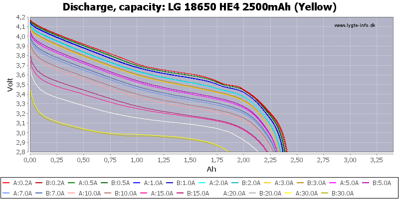
The red discharge curve corresponding to 0.2 A discharge current has been used, whereas the values of  were assigned such that:


- …

is calculated as follows:


- …

The remaining capacity and charge duration are derived as follows:


Where  is the battery design capacity and is the nominal charging current. Note that is increased by 30 % and is increased by 45 minutes in order to to account for resistive losses and estimation inaccuracy.
Safety
The charger implements several safety features. These include undervoltage, overvoltage, short circuit and open circuit detection.
The typical voltage range where a Li-Ion battery can safely operate is between  and
and  . Operating outside this range is likely to cause permanent damage to the Li-Ion cells and may even result in a catastrophic failure such as an explosion or fire.
The battery pack is additionally protected by a battery protection board (or Battery Management System aka BMS). The BMS measures the voltages of the individual battery cells as well as the charge/discharge current flowing through the battery. The BMS uses a solid-state switch to disconnect the battery as soon as the voltage or current values become outside of the specified limits.
For the most part, the BMS is completely transparent and does not interfere with the charging process, except for the case where the BMS disconnects the depleted battery in order to prevent overdischarge. In this case, the voltage of the depleted battery is still present across the BMS terminals through a high value resistor placed in series with the battery. This high value resistor causes a much lower voltage value to be measured at the charger terminals. Consequently, the charger must ignore the  lower limit and start charging at a much lower value of as low as
  .
.
When presented with a depleted battery, the charger would start charging at a reduced safety current  until the battery voltage reaches
  , afterwards it would apply the full charging current . Once the voltage reaches this threshold, it is no longer allowed to drop below the . A voltage below would raise an “undervolt error” which is may caused by either a short circuit or a battery open circuit.
Open circuit is also detected if the charging current stays equal to zero while the PWM duty cycle increases beyond a specific threshold. This condition would raise an “open circuit error”.
Overvoltage is detected whenever the battery pack voltage momentarily exceeds  . Exceeding this value would raise an “overvolt error”.
Trickle Charging
Once the end of charge (EoC) criteria has been met, the charger would cut off the charging current and switch to an idle mode where it will continuously monitor the battery voltage. Once the voltage drops below a specific threshold of  , a new charging cycle will be initiated using the following parameters:


Where is the battery design capacity.  and
and  are the accumulated charge capacity and charge time since the battery has been connected, including the initial charge and all of the subsequent trickle charge cycles.
Given the above formulas, the trickle charge cycle uses a reduced and allows for charging up to a maximum of 3 % of the battery design capacity during a maximum duration of 20 minutes.
Hardware
The following sections describe the hardware design aspects of the Li-Ion charger.
Mechanical Design
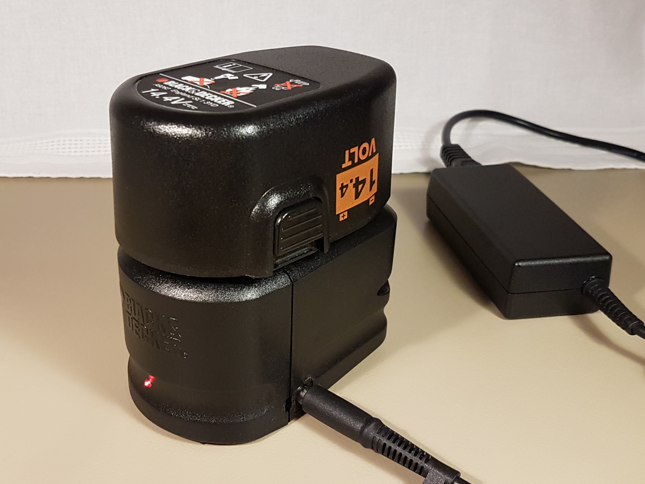
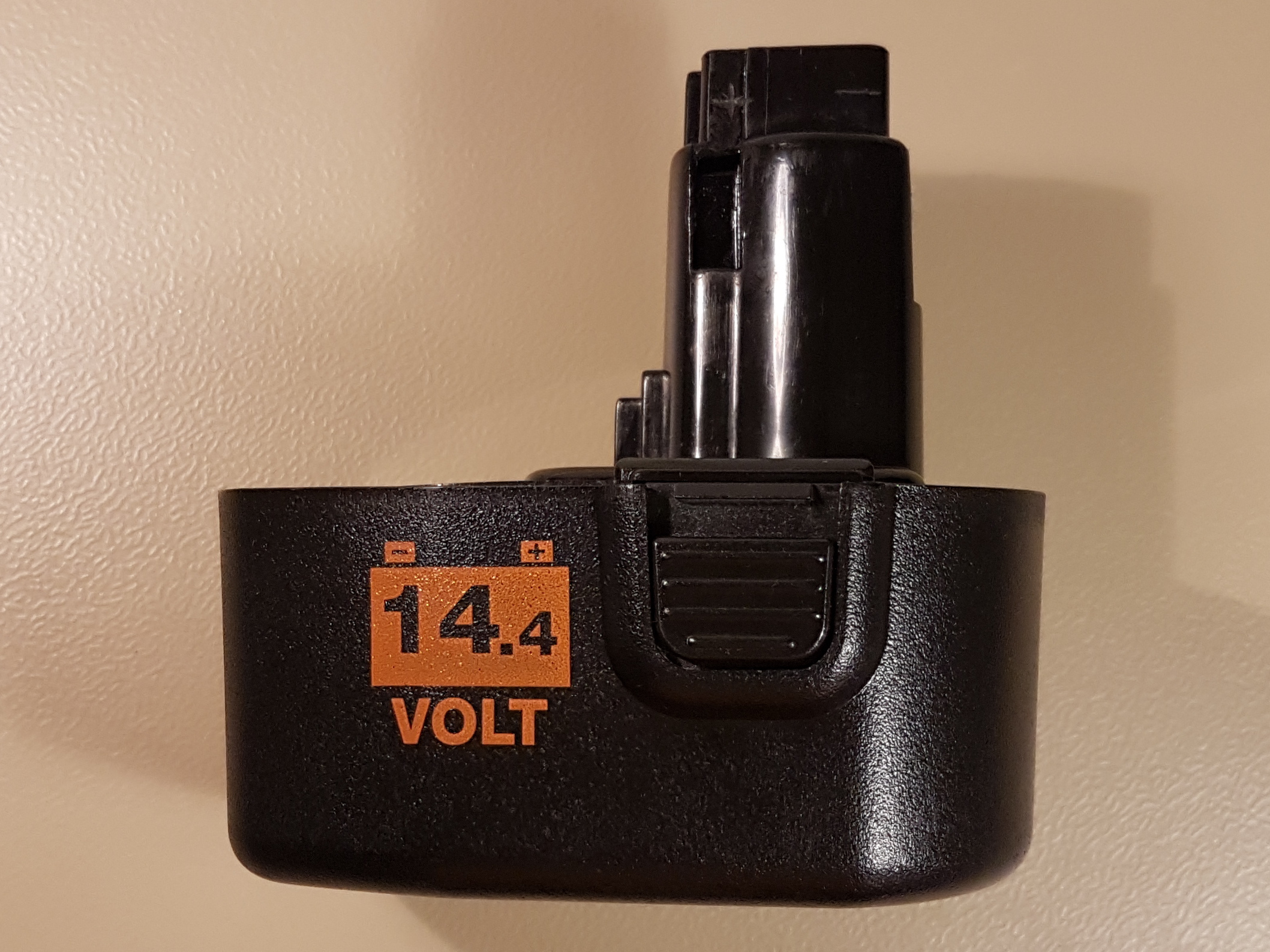
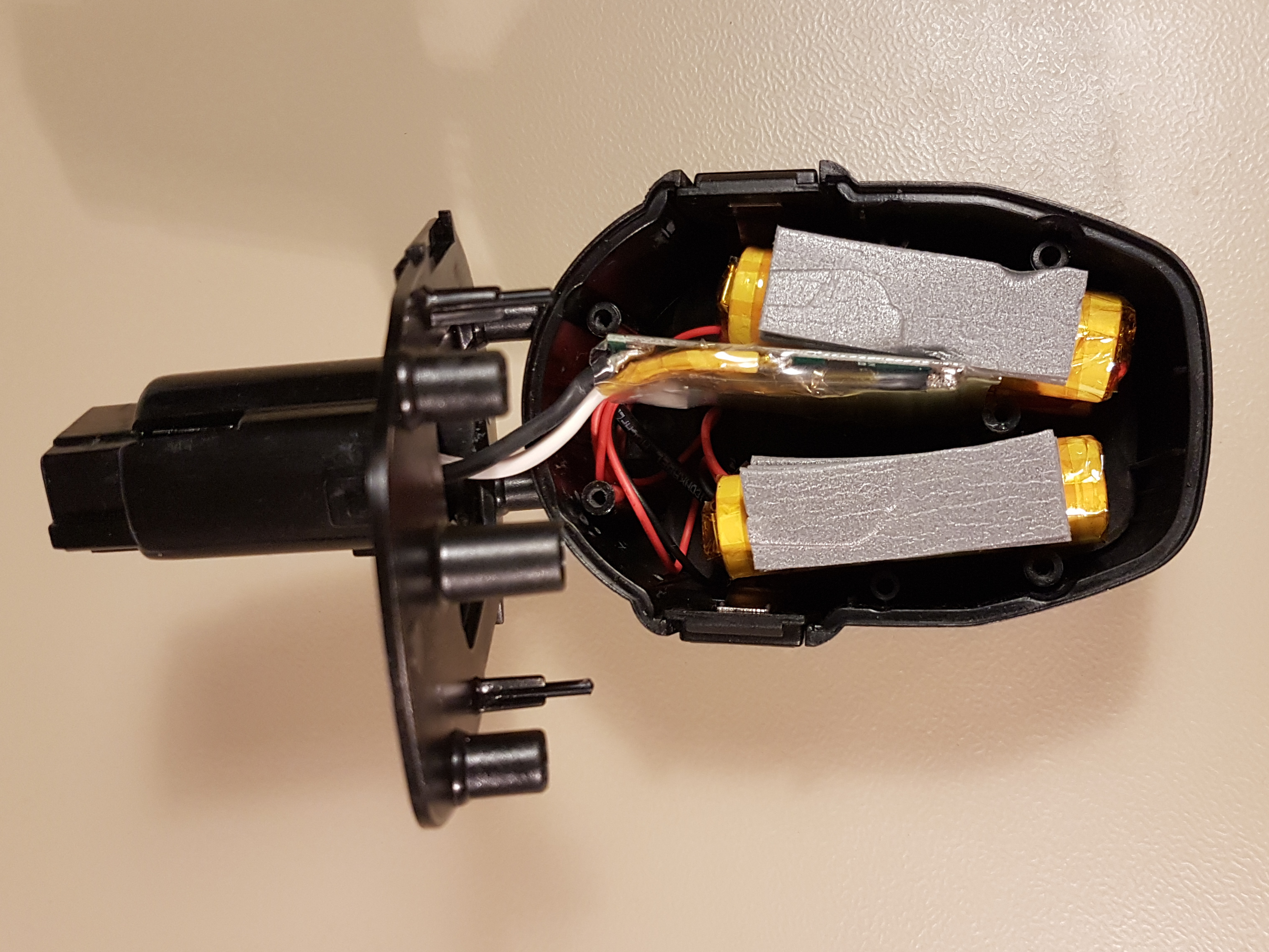
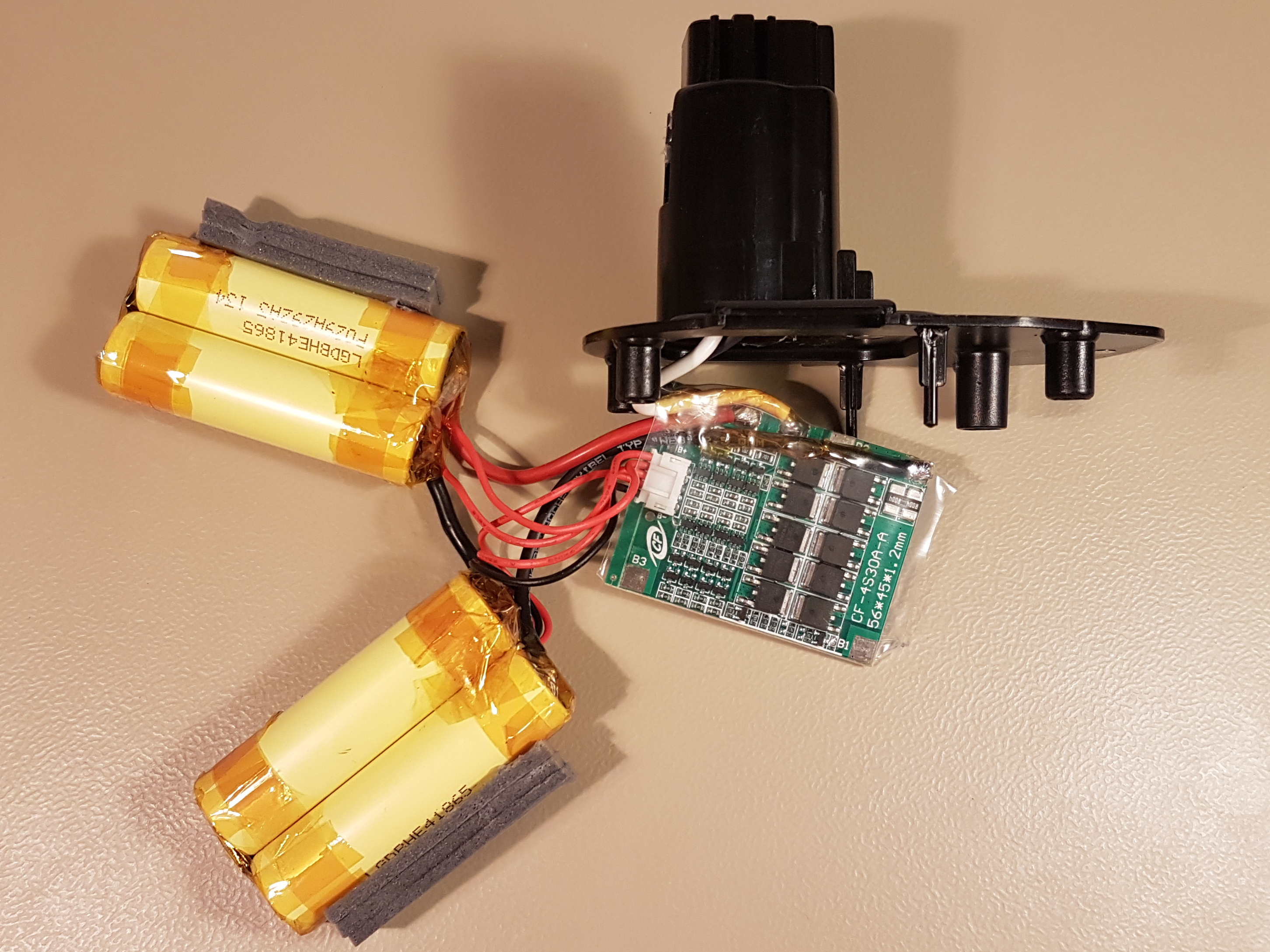
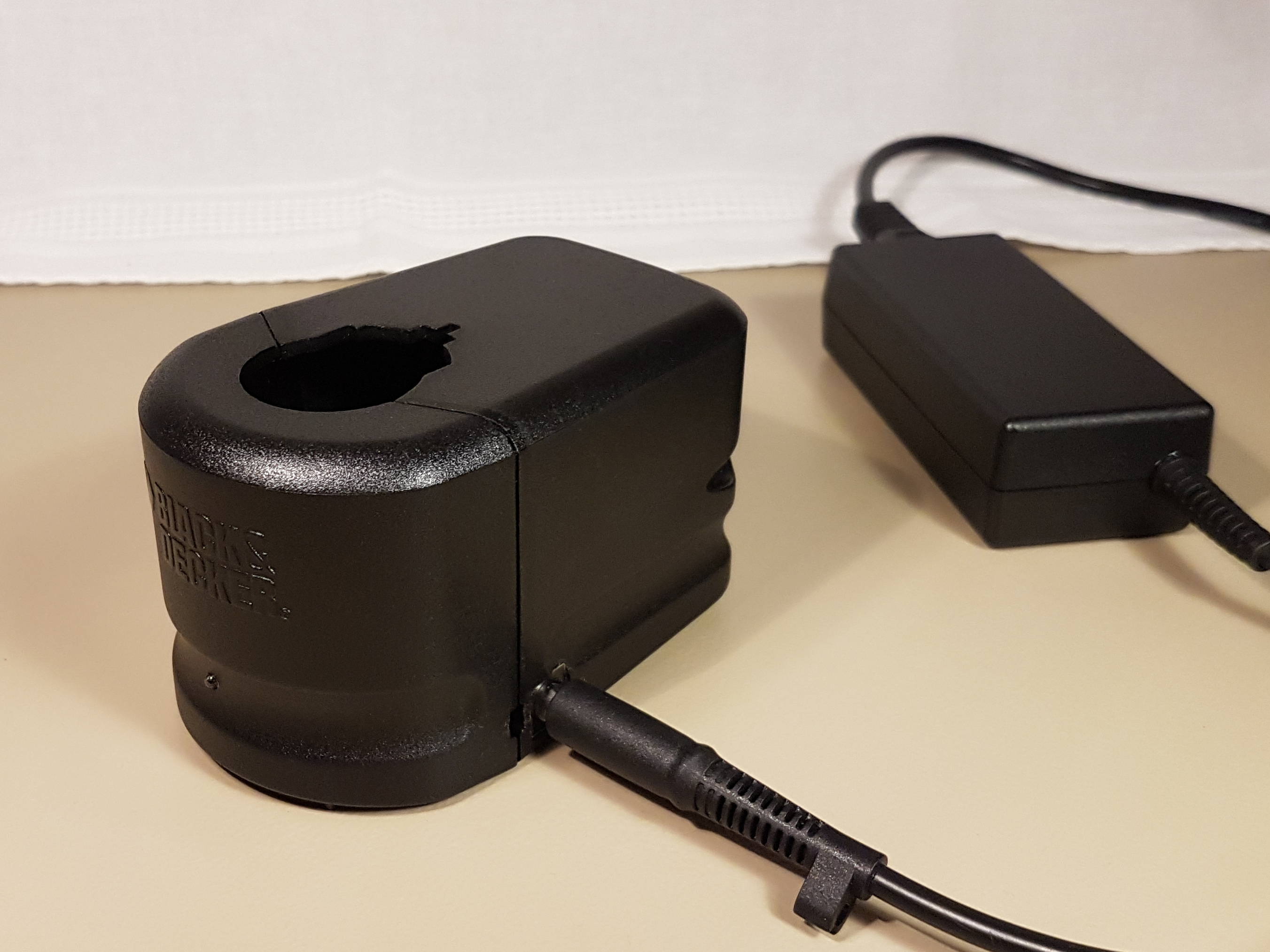
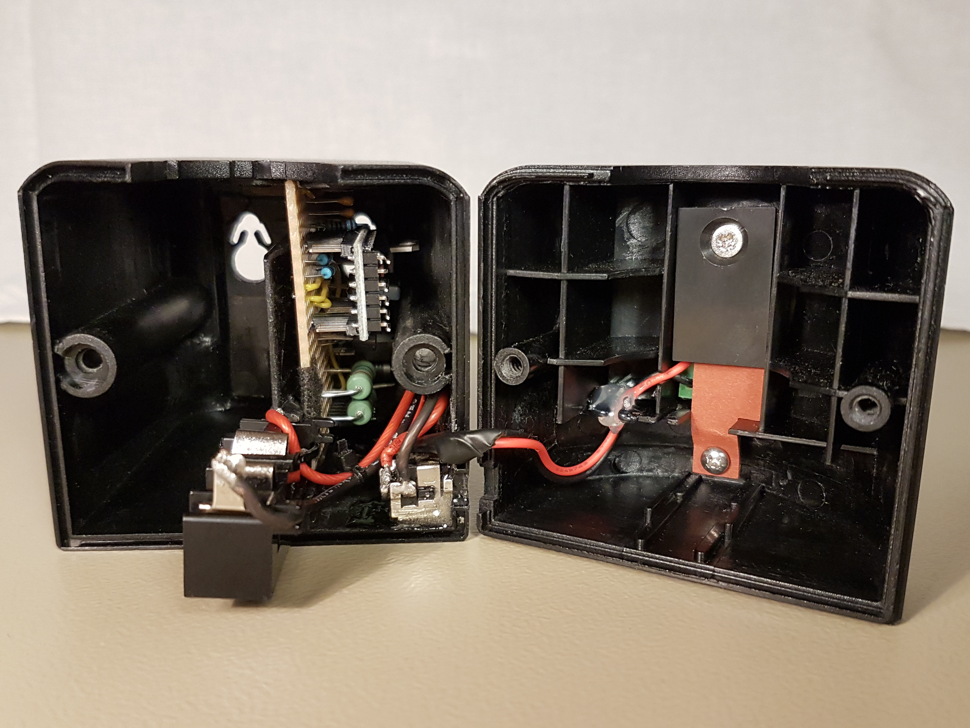
The following image gallery shows the mechanical design of both battery pack and charger.
The original 12 NiCd cells have been removed from the battery pack and replaced by 4 LG 18650 HE4 Li-Ion cells and a battery protection board (or Battery Management System aka BMS). Despite the increased capacity, the modern Lithium-Ion cells use significantly less space which leaves plenty of room for the BMS and the required wiring.
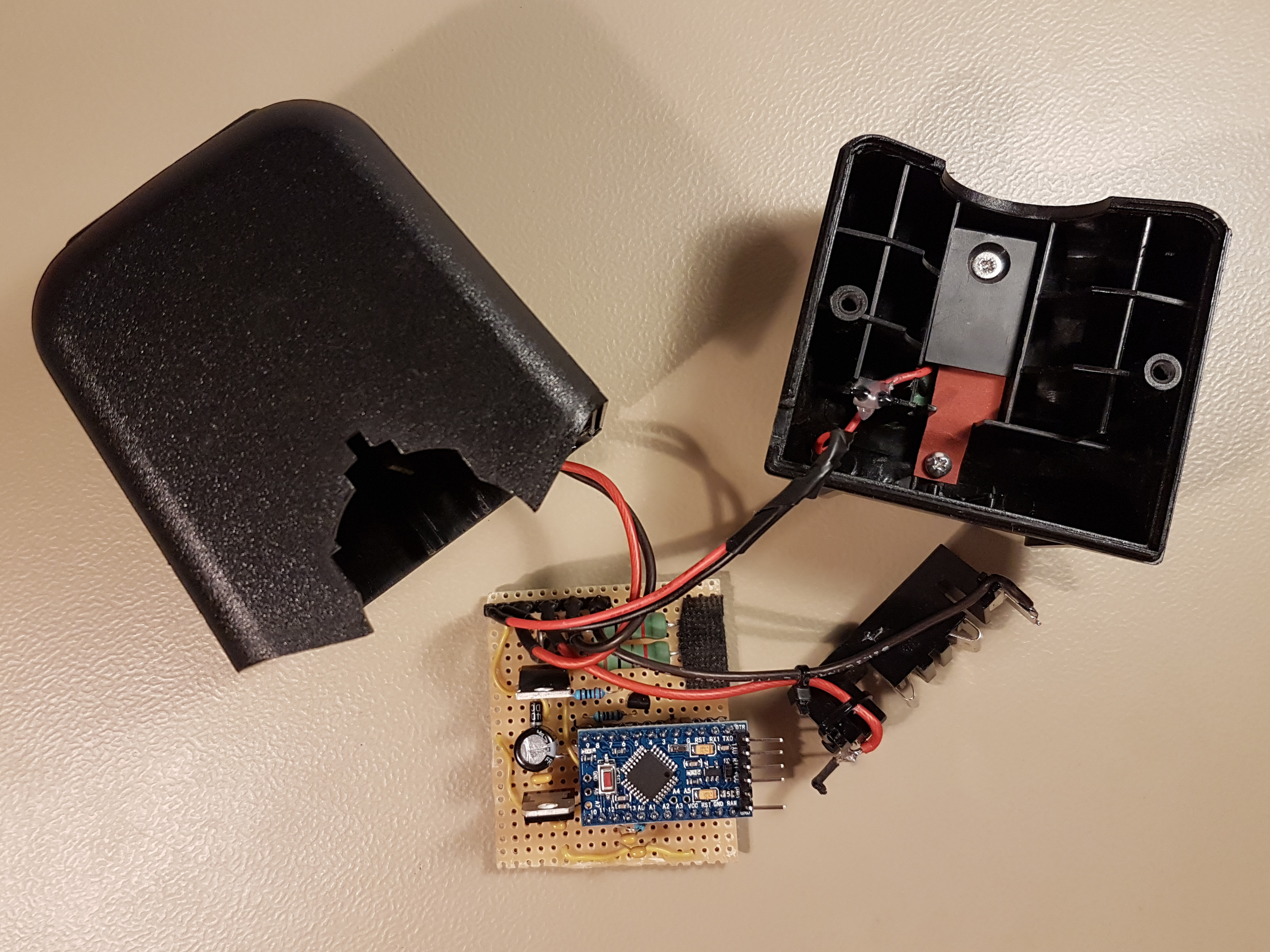
The original battery charger has been retrofitted with the custom PCB containing the Arduino and required circuitry. A 19.5 V / 3.33 A notebook power supply has been used for powering the whole system.
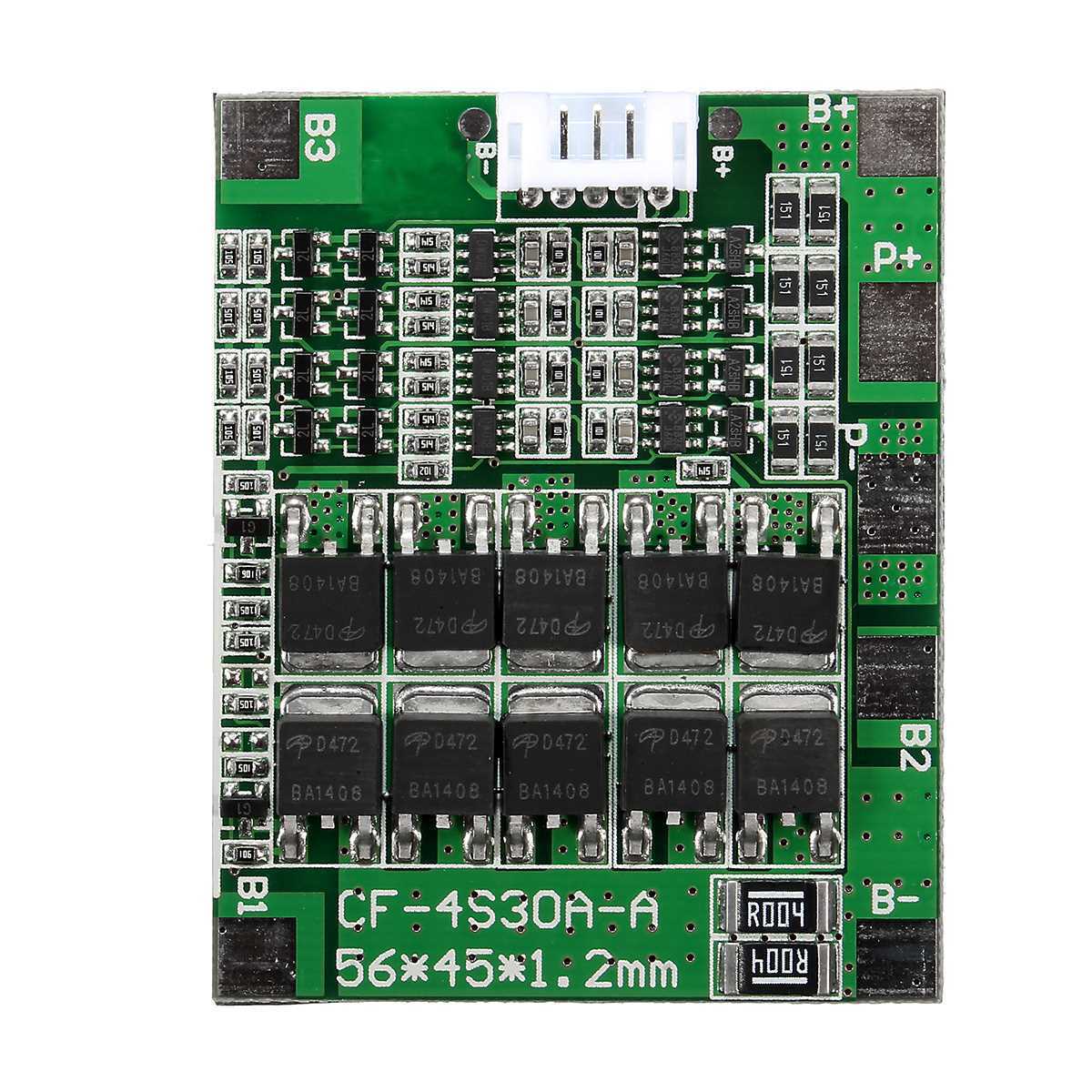
Battery Protection Board
Despite the safety features described above, it is imperative to use a dedicated battery protection board for each of the battery packs. This provides an additional layer of protection to prevent an overcharge or over-discharge condition due to a software or hardware malfunction.
The following figures show the particular 4 S / 30 A (4 S means 4 cells in series) battery protection board (or BMS) that has been used in this project. It has been acquired for less than 10€ on Ebay.
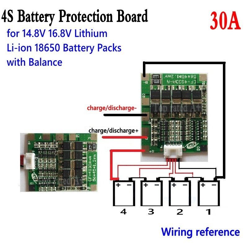
In the above figure one can see the wiring diagram for connection the 4 Li-Ion cells with the BMS.
This particular BMS includes the cell balancer feature. If the voltage of one or more cells becomes higher than the rest of the pack, the BMS would actively discharge those cells to ensure that all the cells of the battery pack share the exact same voltage.
Circuit Diagram
The the following figure shows the Li-Ion charger circuit diagram.
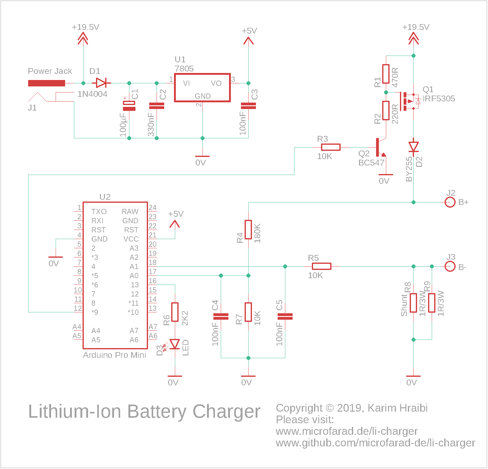
The above schematic, the 19.5 V of the power supply are stepped-down to 5 V by the 7805 voltage regulator U1. The 5 V is used for powering the Arduino board.
The Arduino Pro Mini compatible board U2 hosts an ATmega 328P microcontroller running at 16 MHz clock frequency and is used as the main processing unit for the device.
The Lithium-Ion battery is connected across the B+ and B- terminals. The battery charging current is regulated by switching P-Channel MOSFET (field-effect transistor) Q1 via pulse-width modulation (PWM).
The PWM-enabled digital output pin 9 on the Arduino generates a PWM signal which drives the gate of the MOSFET Q1 through the NPN transistor Q2. The voltage divider formed by R1 and R2 ensures that the gate-source voltage of the MOSFET stays within the specified limits.
A current sensing shunt resistor connects the B- terminal with ground. It consists of two 1 Ω / 3 W resistors R8 and R9 connected in parallel. This results in a total resistance of 0.5 Ω. At a charging current of  , the voltage across the shunt will be exactly 1 V; which is slightly below the 1.1 V internal voltage reference of the Arduino thus corresponds to the full range of the Arduino’s analog-to-digital converter (ADC).
The analog pin A0 on the Arduino is used for measuring the voltage between B+ and 0 V. Analog pin A1 is used for measuring between B- and 0V.
B+ is connected to pin A0 through a voltage divider consisting of R4 and R7, the ratio has been chosen such that the maximum battery pack voltage of 16.8 V would result in slightly less than the Arduino’s internal reference voltage of 1.1 V at A0. Please note that the value of R4 needs to be adapted to the number of cells in use. For example, using a 1 cell setup would require reducing the value of R4 to 39 KΩ.
B- is connected to A1 through a current limiting resistor R5; a voltage divider is not required for measuring as its value stays below the Arduino’s ADC internal reference voltage.
Two 100 nF capacitors C4 and C5 are used for blocking the high-frequency noise caused by the PWM from reaching the analog inputs, an essential measure for smooth ADC readings.
The Diode D1 protects the 7805 regulator from a reverse power supply polarity. The diode D2 protects the battery from a reverse polarity; it also prevents the battery from feeding power back into the Arduino in case the main power supply has been disconnected.
A LED indicator D3 and its dropper resistor R6 are connected to Arduino’s digital pin 13.
Important: The battery terminals in the circuit diagram are labeled as B+ and B-. It is important to connect these terminals to the P+ and P- terminals of the Battery Management System (BMS) depicted in the picture. The BMS has its own set of B+ and B- terminals that must be connected directly to the battery terminals. It is crucial to avoid connecting the charger’s B+ and B- terminals to the B+ and B- terminals of the BMS, as this would bypass the BMS and prevent it from safeguarding the battery against overcharging.
Different Number of Cells
The following values for R2, R4 and the power supply voltage need to be chosen in order to charge different numbers of Cells:
 | Power Supply | R2 | R4 |
| 1 * | 5 V-6 V | 220 Ω * | 39 KΩ |
| 2 | 10 V – 15 V | 100 Ω | 82 KΩ |
| 3 | 14 V – 20 V | 220 Ω | 120 KΩ |
| 4 | 18.5 V – 20 V | 220 Ω | 180 KΩ |
* When charging 1 cell, the following circuit modifications must be performed:
- Remove the voltage regulator U1 and capacitor C3 and power the Arduino directly from the output of D1
- Replace Q1 with a IRLML2244 MOSFET
- Increase R1 to 10 KΩ
- Remove Q2 and R3
- Connect R2 directly to Arduino digital pin 9
- Modify the code in
li-charger.inoto invert the PWM signal by subtracting the PWM duty cycle from 255 within all instances ofanalogWrite()using one of the following statements:
analogWrite (MOSFET_PIN, 255 - G.dutyCycle);  // Replaces analogWrite (MOSFET_PIN, G.dutyCycle)
analogWrite (MOSFET_PIN, 255);                // Replaces analogWrite (MOSFET_PIN, 0)
PCB Layout
All of the components are of through-hole type and are mounted on a stripboard PCB. The following figures show the PCB layout of the Li-Ion charger (click to enlarge).
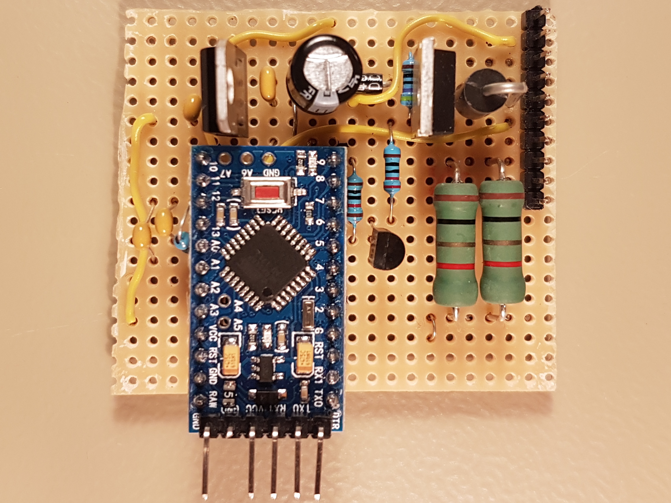
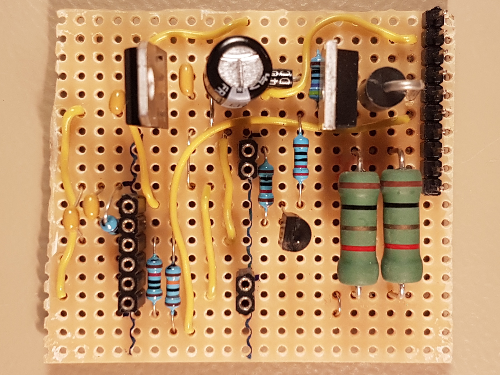

The MOSFET Q1 (TO-220 device in the top right corner) and large green-colored shunt resistors will get pretty hot so adequate ventilation needs to be assured. The following measures has been taken to avoid overheating:
- The shunt resistors R8 and R9 are raised by around 5mm from the PCB in order to assure adequate cooling.
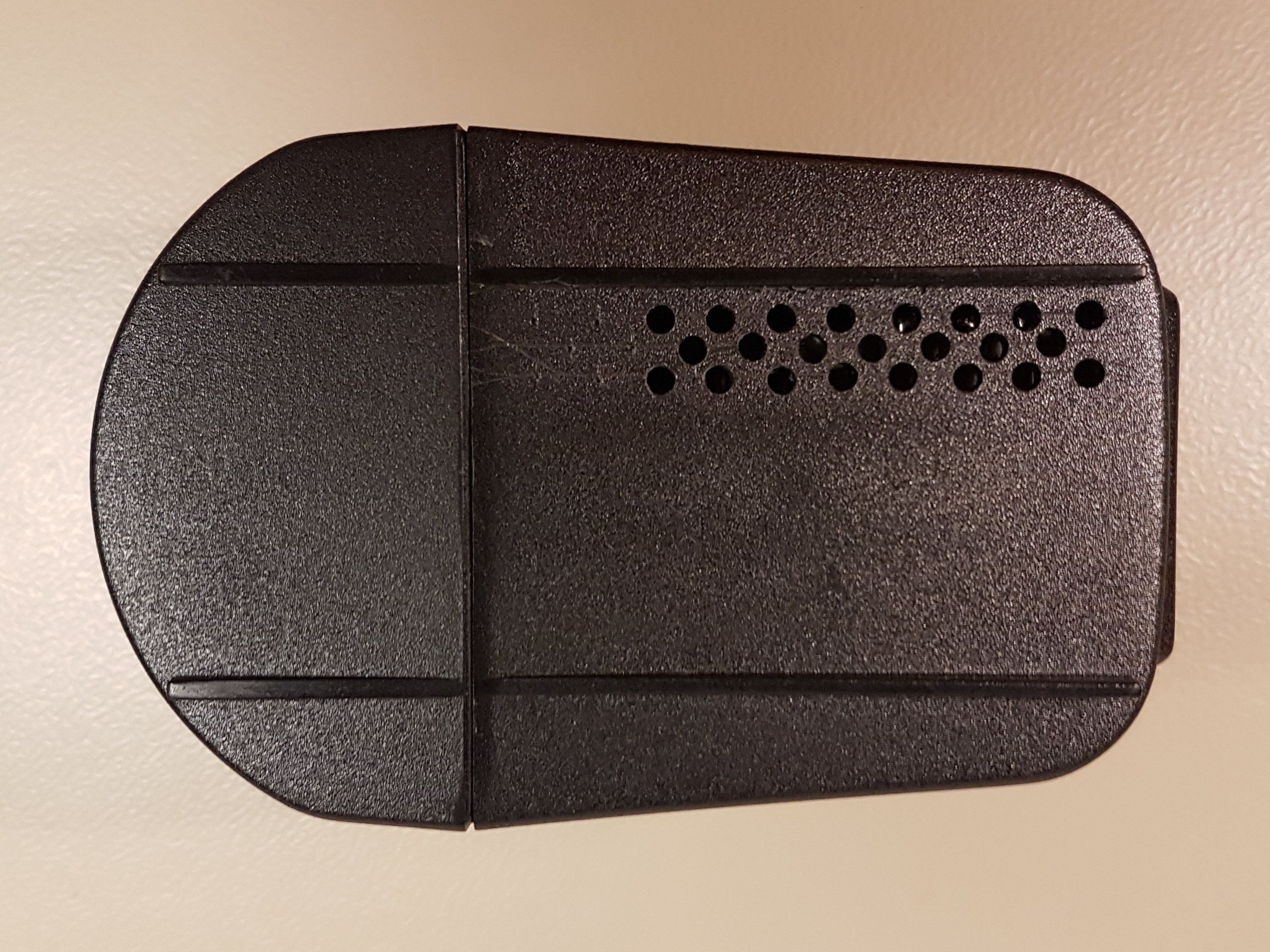
- A series of holes has been drilled in the bottom of the enclosure in order to allow for a better air flow.
- The charging current has been limited to 1.5 A.
The electrolytic capacitor C1 towards the top center of the board is in a suboptimal position due to its location between two hot components – the 7805 regulator and the MOSFET. High temperatures reduce the lifespan of electrolytic capacitors thus the must be kept away from heat sources.
The pin header located at the top right corner is used for connecting all the external wires. Following is the pinout assuming that pin 1 is at the top right corner and pin 10 is towards the middle of the board.
| Pin | Purpose |
| 1 * | LED + |
| 2 * | LED – |
| 3, 4 † | Power supply + |
| 5, 6 † | Battery + |
| 7, 8 † | Power supply – |
| 9, 10 † | Battery – |
* The LED dropper resistor is located on a separate PCB together with the LED itself.
† Two pins are connected in parallel in order to increase their current capacity.
User Interface
The following sections describe the user interface of the Lithium-Ion charger. It consists of a LED indicator and a Command-Line Interface (CLI).
LED Indicator
The charger status is displayed by means turning on or blinking a single LED as shown in the following table.
| Blinking Pattern | Meaning |
| On for half a second every 2 seconds | Ready, waiting for the battery to be connected |
| Solid on | Battery charging |
| On for 0.1 second every 2 seconds | Battery fully charged |
| Blinking fast (0.4 s period) | Error |
| Blinking very fast (0.2 s period) | Calibration mode |
Command-Line Interface
This Lithium-Ion battery charger features a Command-Line Interface (CLI) that can be accessed via the Arduino’s RS232 serial port. The easiest way to connect to the CLI is to open the serial monitor of the Arduino IDE while connected to the charger using a FTDI USB to Serial converter. Please ensure that the Baud rate is set to 115200.
Once up and running, the charger will display a welcome message on the serial monitor, show the current firmware version and present with the list of available commands shown in the following table.
Some of these CLI commands need to be provided with arguments. Thus, one needs to enter a the command followed by one or two arguments separated by a white space.
| Command | Description |
h | Help – show the list of available commands |
. | Display the real-time parameters, including the charge duration , charge capacity , battery voltage , charging current , maximum charge duration , maximum charge capacity , maximum charging voltage , maximum charging current  , PWM duty cycle, voltages , and their raw ADC values , PWM duty cycle, voltages , and their raw ADC values  and and  |
r | Show the list of calibration constants that are stored within EEPROM |
t | Show the contents of the trace circular buffer |
ncells <integer> | Set the total number of cells within the battery pack , the value provided as an argument will be validated and stored in EEPROM |
cfull <integer> | Set the battery design capacity in mAh, the value provided as an argument will be validated and stored in EEPROM |
ichrg <integer> | Set the battery charging current , the value provided as an argument will be validated and stored in EEPROM |
ifull <integer> | Set the end of charge current in mA, the value provided as an argument will be validated and stored in EEPROM |
lut <index> <voltage> | Configure the state of charge lookup table (LUT). This command takes and index  and the reference voltage and the reference voltage  in mV as arguments. Each time this command is called, a new reference voltage value is populated into the LUT and stored into EEPROM, more on this in the following section in mV as arguments. Each time this command is called, a new reference voltage value is populated into the LUT and stored into EEPROM, more on this in the following section |
rshunt <integer> | Set the shunt resistor value in mΩ, The value provided as an argument will be validated and stored in EEPROM |
cal <start| stop| v1| v2> [mv] | The voltage calibration mode is entered by calling cal start and exited by calling cal stop. is calibrated using is calibrated using cal v1 <mv>. is calibrated using is calibrated using cal v2 <mv>.<mv> is the measured voltage level in millivolts. Please refer to the next section for more details about the calibration procedure. |
Calibration Procedure
This section provides an example on how to perform the first-time calibration of the Lithium-Ion battery charger using the CLI over the serial monitor.
The calibration values are stored into the Arduino’s electrically erasable programmable read-only memory (EEPROM). A cyclic redundancy check (CRC) checksum is appended to the configuration parameters set and stored into EEPROM as well. All configuration parameters are validated and out-of-range values are automatically replaced with the corresponding failsafe values.
The current example assumes a system consisting of  connected in series having a design capacity of
  charged using a current of
  .
.
Important:
- Do not connect the battery during the calibration procedure unless instructed otherwise.
- Ensure that the voltage calibration procedure has been properly executed and verified prior to attempting to connect a Lithium-Ion battery. It is mandatory to connect a good quality battery protection board between the charger and battery. Failing to observe these precautions may lead to permanent damage or even explosion of the Lithium-Ion cells.
Initial Configuration
A a first step, the initial configuration parameters need to be loaded into EEPROM by executing the command sequence below:
ncells 4
cfull 2500
ichrg 1500
ifull 150
rshunt 500
lut 0 3200
lut 1 3450
lut 2 3530
lut 3 3610
lut 4 3650
lut 5 3710
lut 6 3825
lut 7 3920
lut 8 4020
A confirmation message will be printed on the serial monitor following each value entry.
Voltage Calibration
Having performed the above initial step, please proceed for calibrating the ADC readings for the voltages , as shown below:
- Enter the command
cal startinto the serial monitor, this will activate the calibration mode. The messageCalibration startshould appear on the serial monitor. - Connect a constant voltage source of approximately 750 mV between the B- terminal and the power supply ground (0 V) and measure its exact value using a digital multimeter. Note that 750 mV corresponds to 1.5 A flowing through the shunt resistors R8 and R9. Note: If your power supply is unable to deliver 1.5 A of current, then temporarily disconnect the shunt resistors R8 and R9.
- Enter the command
cal v2 <value>into the serial monitor, where<value>is the value in mV of the voltage measured in the previous step (e.g. 854). The value of the calibration constant will be displayed upon the successful calibration of . If the calibration fails, the message
 Out of rangewill appear in the serial monitor. - Connect a constant voltage source of approximately 16800 mV (4200 mV per cell) between the B+ terminal and the power supply ground (0 V) and measure its exact voltage using a digital multimeter.
- Enter the command
cal v1 <value>into the serial monitor, where<value>is the value in mV of the voltage measured in the previous step (e.g. 16450). The value of the calibration constant will be displayed upon the successful calibration of . If the calibration fails, the message
 Out of rangewill appear in the serial monitor. - Verify the voltage calibration by applying a known voltage to each of B+ and B- (relative to 0 V), then enter the
.(dot) command and check the displayed values for and which must match the measured voltages at B+ and B- as closely as possible. - Repeat steps 2, 3, 4, 5 and 6 until the voltage readings are correct.
- Enter the command
cal stopin order to exit the voltage calibration mode. The messageCalibration stopshould appear on the serial monitor.
Current Calibration
Please proceed with calibrating the reading of the current by following the steps below:
- Connect a discharged Lithium-Ion battery to in series with a digital ampere meter (set to the 10 A range) to the terminals B+ and B-.
- The message
Chargingshould appear in the serial monitor and the measured current value should start to gradually increase until it reaches a maximum of approximately 1.5 A. - Enter the
.(dot) command and check the displayed value for which must match the measured current as closely as possible. - If the output of the
.command is higher than the amperemeter reading: increase the value of by 10 mΩ by calling the rshuntcommand with the original shunt resistance value increased by 10 mΩ. - If the output of the
.command is lower than the amperemeter reading: decrease the value of by 10 mΩ by calling the rshuntcommand with the original shunt resistance value decreased by 10 mΩ. - Repeat steps 3, 4 and 5 until you get an accurate reading of .
Trace Buffer
The Lithium-Ion battery charger logs the events that occur during the charging process into a circular buffer within the available EEPROM space. The contents of the trace buffer are dumped using the t command. Following is a sample trace log output for a complete charging cycle:
  0: * 16760
  0: % 0
  0: v 7820
  0: T 135
  0: C 3263
  0: S 150
  0: I 1500
  2: v 13222
  2: i 1495
  4: v 13719
  4: i 1499
  6: v 13982
  6: i 1495
  8: v 14137
  8: i 1503
 10: v 14206
(skipped...)
100: v 16767
100: i 638
102: v 16764
102: i 529
104: v 16761
104: i 381
106: v 16754
106: i 241
108: v 16759
108: i 231
110: v 16764
110: i 221
112: v 16761
112: i 150
113: F 1
113: t 113
113: c 2508
113: v 16767
113: i 139
The trace messages have the format of <timestamp>: <event> <value>. Whereas the timestamp counts the minutes elapsed since the beginning of the charging process. The following table shows available events and their descriptions:
| Event | Description |
* | Beginning of the charging cycle, indicates the maximum battery voltage in V |
% | Initial state of charge in % |
T | Maximum allowed charge duration in minutes |
C | Maximum allowed charge capacity in mAh |
S | Safety charge in progress, indicates  in mA in mA |
I | Normal charge in progress, indicates in mA |
v | Instantaneous battery voltage  in mV in mV |
i | Instantaneous battery current in mA |
F | Battery full, indicates the end of charge condition (1 = reached, 2 = reached, 3 = reached) |
t | Actual charge duration in minutes |
c | Actual charged capacity in mAh |
E | Error (1 = overvolt, 2 = undervolt, 3 = open circuit, 99 = CRC fail) |
Downloads
Below you can find GitHub download links for the Arduino firmware source code, Eagle schematic source files and bill of material. All of the source code is distributed under the GNU General Public License v3.0.
Please note that the current implementation uses the watchdog timer functionality which requires the customized Arduino bootloader found under the link below. Additionally, ensure that you use Arduino IDE version 1.8.19 to compile the firmware. For more details, please follow the installation instructions found within the README file on GitHub.
Thanks for this detailed submit.
I suppose the code is easily ported across other Arduino flavours, i.e Nano zero?
Best regards,
Serge
Hi Serge,
You are welcome. The design requires two analog inputs, one PWM and one digital output. Both Arduino Zero and Nano meet these requirements, so the firmware should be ported with minimal effort.
Regards, Karim