Following is the tutorial of a DIY magnetic loop antenna for the amateur radio band featuring a remote tuning system implemented on Arduino with a RC servo.
The magnetic loop has a very small form factor and enables decent short wave communication from within buildings and confined spaces where there is no possibility to install any of the larger antenna types that usually would require erecting a tower over the roof or spanning tens of meters of wires across the backyard.
Warning: Magnetic loop Antennas produce dangerously high currents and voltages. During signal transmission, several Kilovolts of voltage are being produced across the capacitor terminals and a current of several tens of Amps is flowing across the loop conductor. Please be aware that this design has not been certified for safety, consequently it is not suitable for commercial applications and must be implemented at your own risk. Please do not attempt this project unless you are fully confident in what you are doing and do possess the required technical skills. The author of this page is not liable for any potential damage to living beings and things that might occur due to the implementation and usage of the magnetic loop.
Table of Contents
Theory
The following figure shows the diagram of a magnetic loop antenna (source: www.i1wqrlinkradio.com/antype/ch9/chiave151.htm).
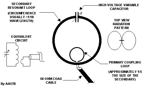
A magnetic loop is essentially a small loop antenna whose circumference is less than 1/10 of the wavelength. The magnetic loop couples to the to the magnetic field of the radio wave in the region near the antenna, in contrast to a monopole or a dipole which couple to the electric field of the wave. When receiving, the oscillating magnetic field of the incoming radio wave induces a current in the loop by Faraday’s law of induction.
The magnetic loop consists of a conductive loop that is separated at one end by a capacitor, thus forming an LC circuit that has to resonate at the operating frequency of the antenna. A smaller loop is positioned towards the opposite end of the capacitor within the area of the main larger loop. This smaller loop is connected to the transceiver via an impedance-matched feed line. Both small and large loops are magnetically coupled and form a transformer. During transmission, the smaller loop would induce a high-frequency AC current into the larger loop that in turn would radiate the RF signal. During reception, the RF signal is picked-up by the larger loop and current is induced into the smaller loop which is fed into the receiver.
The diameter ratio between the both loops determines the impedance of the antenna which must match with the impedance of the feed line and the output impedance of the transceiver. Further, the LC circuit must be resonating at the transceiver’s operating frequency. In order to achieve this, a variable capacitor is used as part of the LC circuit. Failing to have an impedance-matched and resonant circuit would result in the transmitted signal being reflected back into the transceiver’s power amplifier stage, causing possible damage and what is referred-to as a high standing wave ratio (SWR).
When transmitting with 100 Watts of power, the current within the large loop would amount to several Amperes, while the voltage across the capacitor would be in the order of Kilovolts. This high voltage requires quite a large air capacitor with an adequate separation between its plates. Consequently, this magnetic loop has been built around an old heavy duty Soviet-made variable capacitor originating form some vintage radio equipment.
Since the antenna is typically located several meters away from the radio operator, there must be a way to remotely tune the variable capacitor. This has been achieved by attaching a standard RC grade servo to the capacitor’s shaft and remotely controlling it via a control unit implemented around an Arduino Pro Mini. As one might guess, a significant part of the overall effort went into implementing the remote control system which must comply with the following major requirements:
- It must be precise enough to tune the antenna as close to the operating frequency as possible in order to achieve a reasonably low SWR.
- It must be immune to the very high radio frequency (RF) interference present in the vicinity of a transmitting antenna.
The following sections describe the design of the magnetic loop antenna in more detail.
Specifications
Following are the main specifications of the magnetic loop antenna:
- Operating bands: 60 m, 40 m, 30 m, 20 m, 17 m, 15 m
- Maximum Tx power: 100 W
- System weight: 5 Kg
- Main loop: 3,94 m circumference, made of Ecoflex 15 cable (15 mm diameter coaxial cable)
- Coupling loop: 10 mm² solid copper wire with adjustable diameter in two different versions:
- For outdoor use: 20 cm – 30 cm diameter
- For indoor use: 40 cm – 50 cm diameter
- Tuning capacitor: Soviet-made dual air capacitor with 2x 14 pF .. 450 pF connected in series
- Tuning motor: “MG946R” digital RC servo with metal gears
- Control unit: Arduino Pro Mini, 4 AA batteries, with 3 push buttons and a fine-tuning potentiometer
- Mast: 2 cm PVC pipes, metal tripod
Mechanical Design
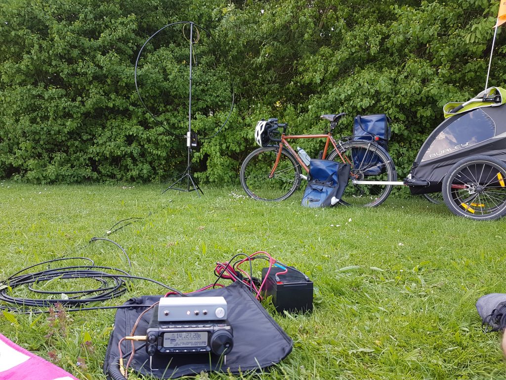
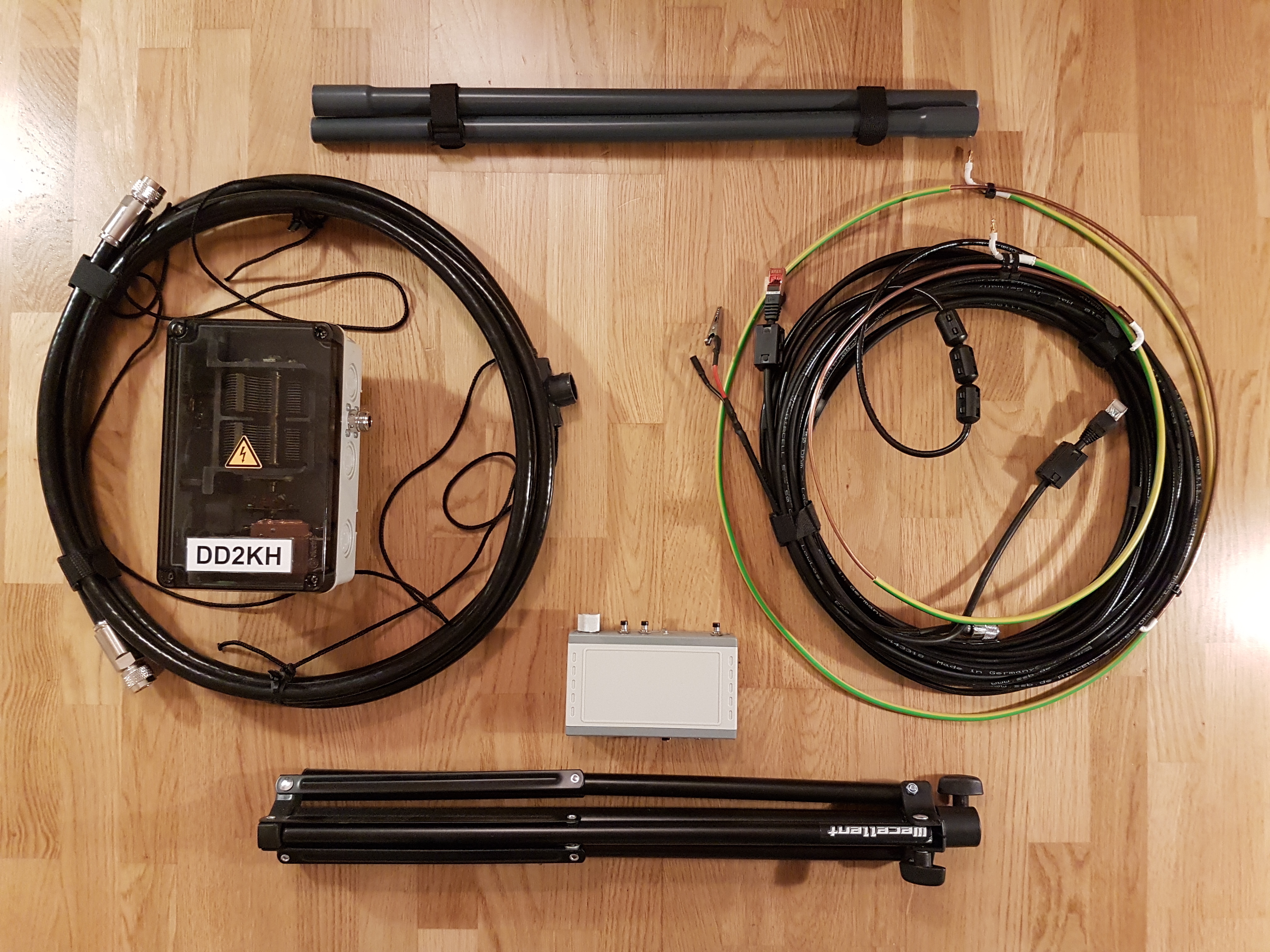
The following pictures show the antenna in both assembled and disassembled states.
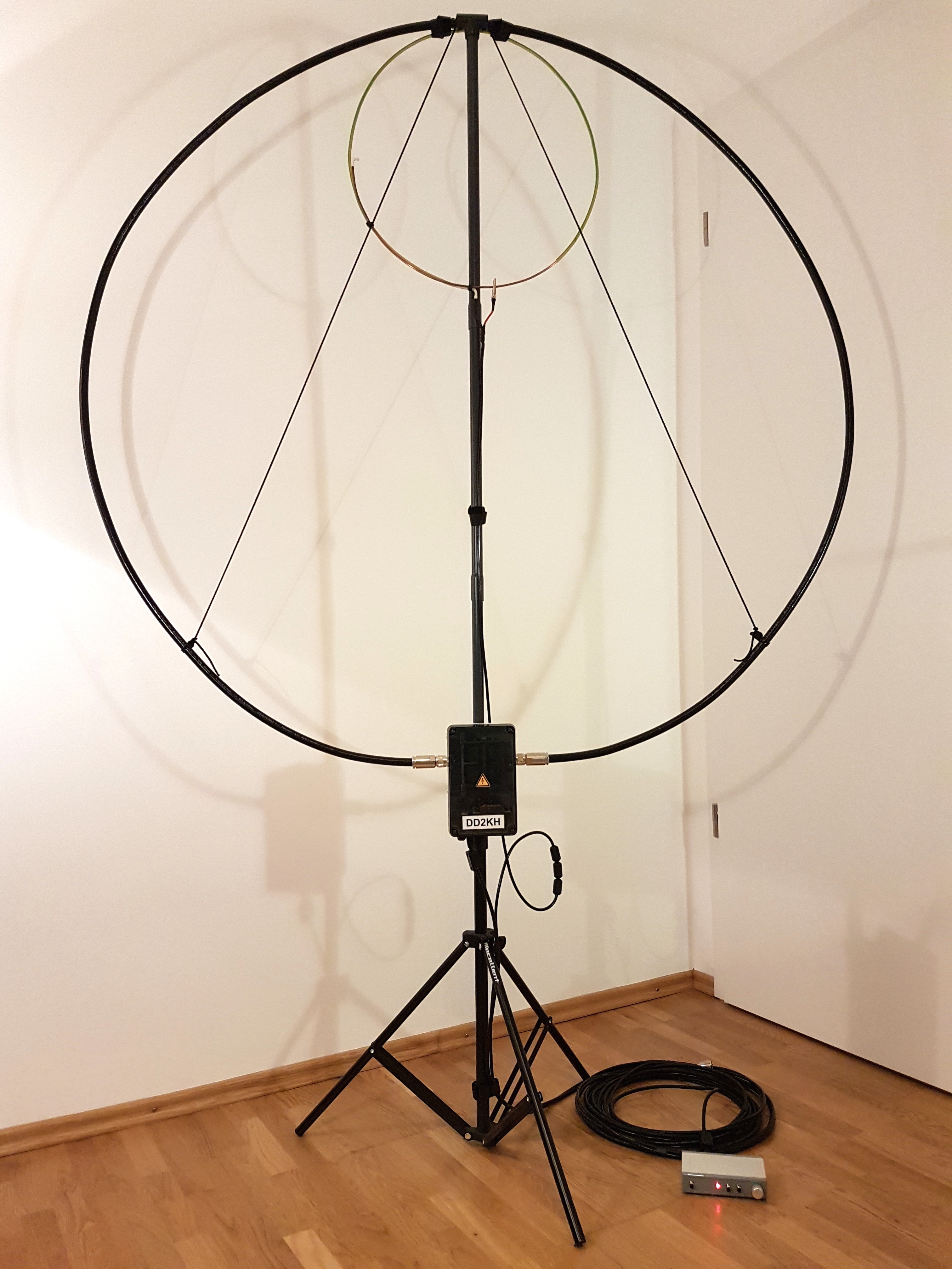
As shown in the above picture, the main loop formed out of the Ecoflex coaxial cable is secured to the top of the PVC pipe using a T-joint. The coaxial cable is connected to both sides of the capacitor box which is located at the bottom of the mast. The inverted-V shaped nylon rope supports the main loop and ensures that its shape resembles a circle.
The coupling loop is secured using Velcro strips at the top of the main loop. The centre wire of the feed line coaxial cable is connected to the coupling loop using a crocodile connector, this enables accurate impedance matching by moving the feed line connection point along the perimeter of the coupling loop.
When operating the magnetic loop within a building, capacitive coupling to metal parts within the reinforced concrete walls, window frames and other objects significantly affect the tuning of the antenna. Whereas a much larger coupling loop is required for indoor operation. Consequently, two coupling loops with different diameters were constructed for indoor and outdoor use.
In order to avoid any loss of efficiency, as few metal parts as possible have been used in constructing the antenna mast, thus the choice of using PVC tubes instead of a full-height retractable metal tripod. A short metal tripod is used to support the PVC mast from below (less than ideal, however no practical alternative was found).
The variable capacitor is remotely controlled through a control unit that is placed besides the transceiver. The control unit is connected with the capacitor using a 10 meter shielded Ethernet cable.
Motorized Capacitor
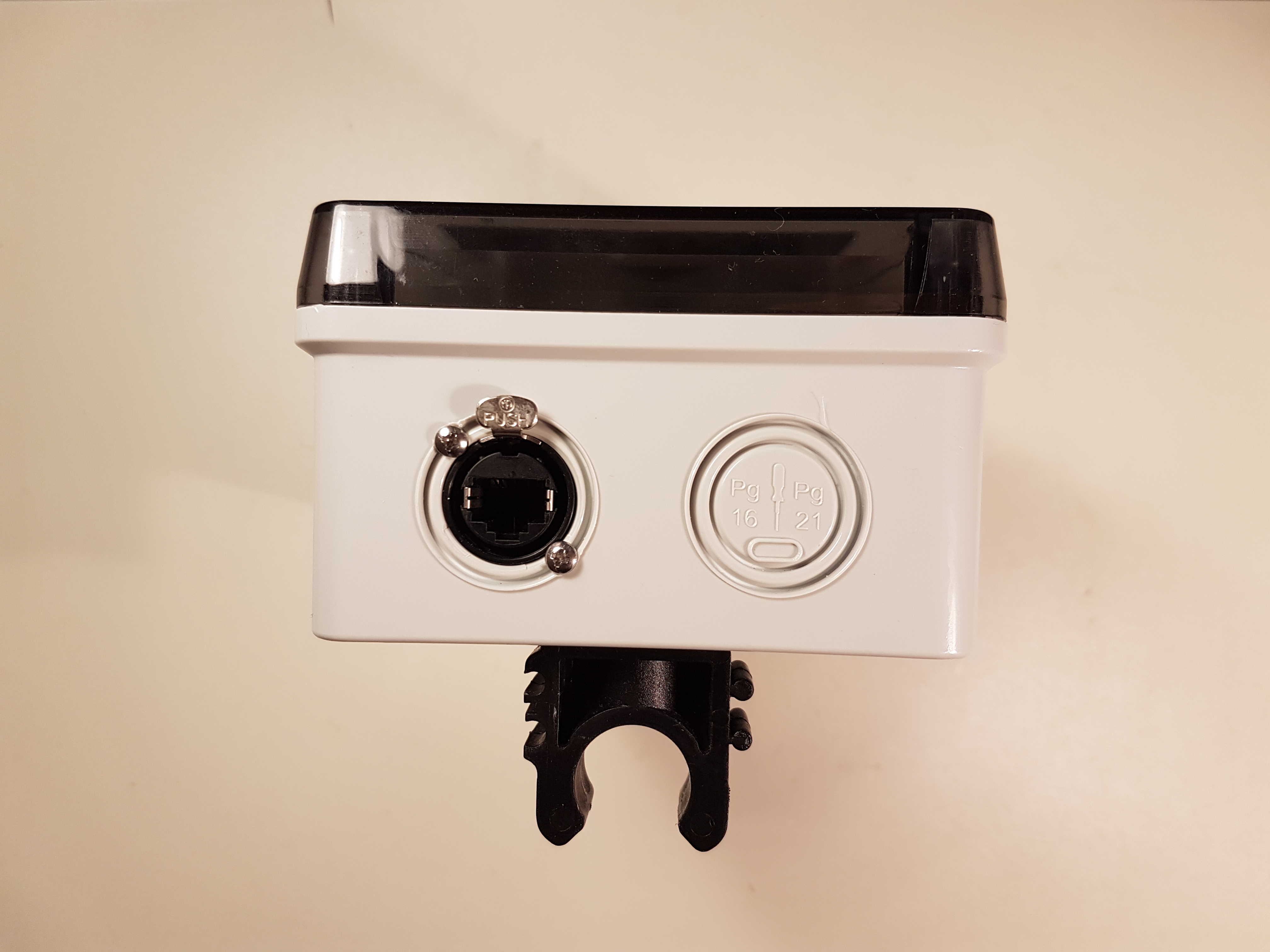
The variable air capacitor and the RC servo are installed within an IP67 rated water-proof enclosure with the dimensions 180 x 110 x 70mm. The following pictures show the details of the capacitor box.
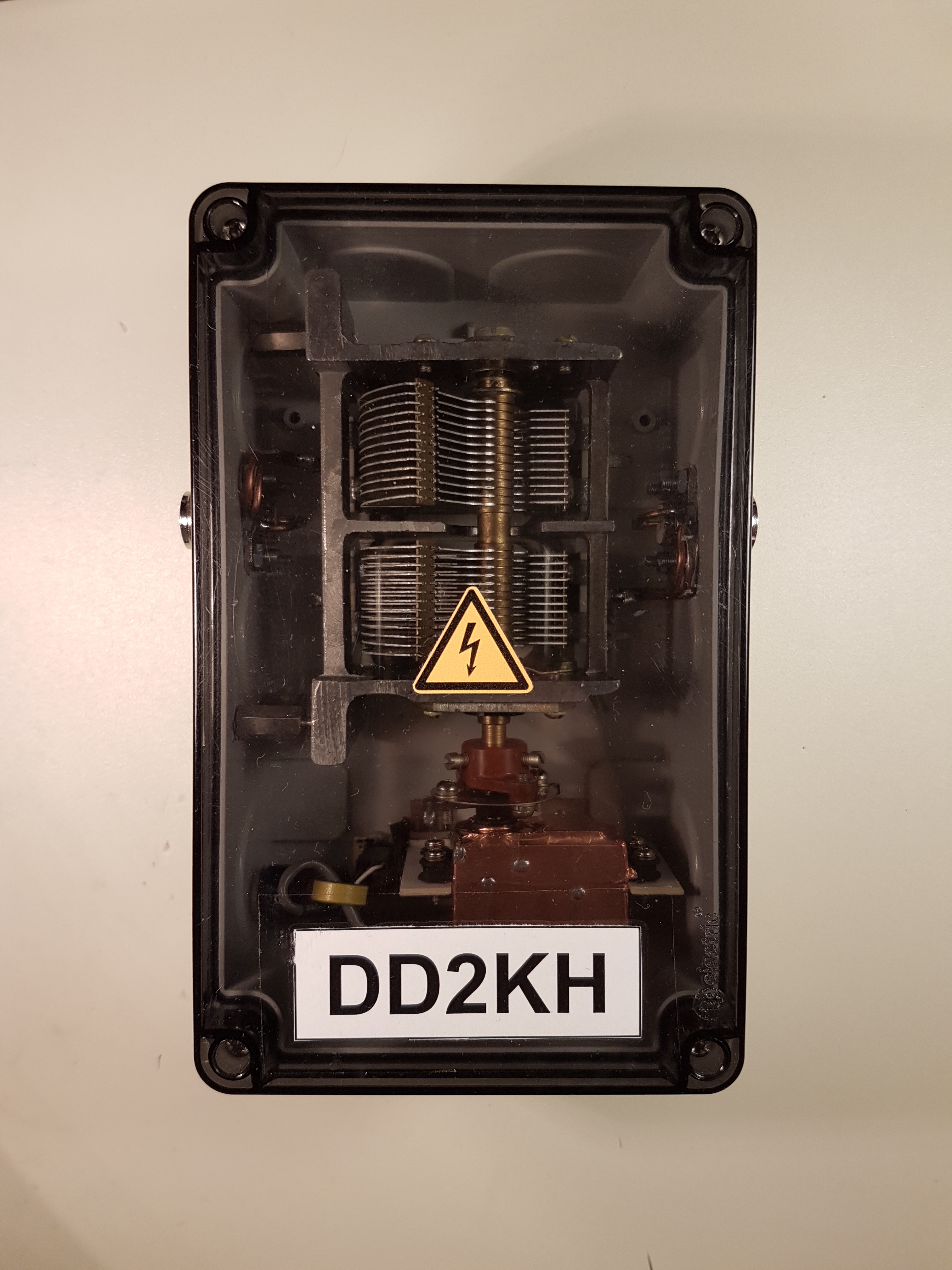
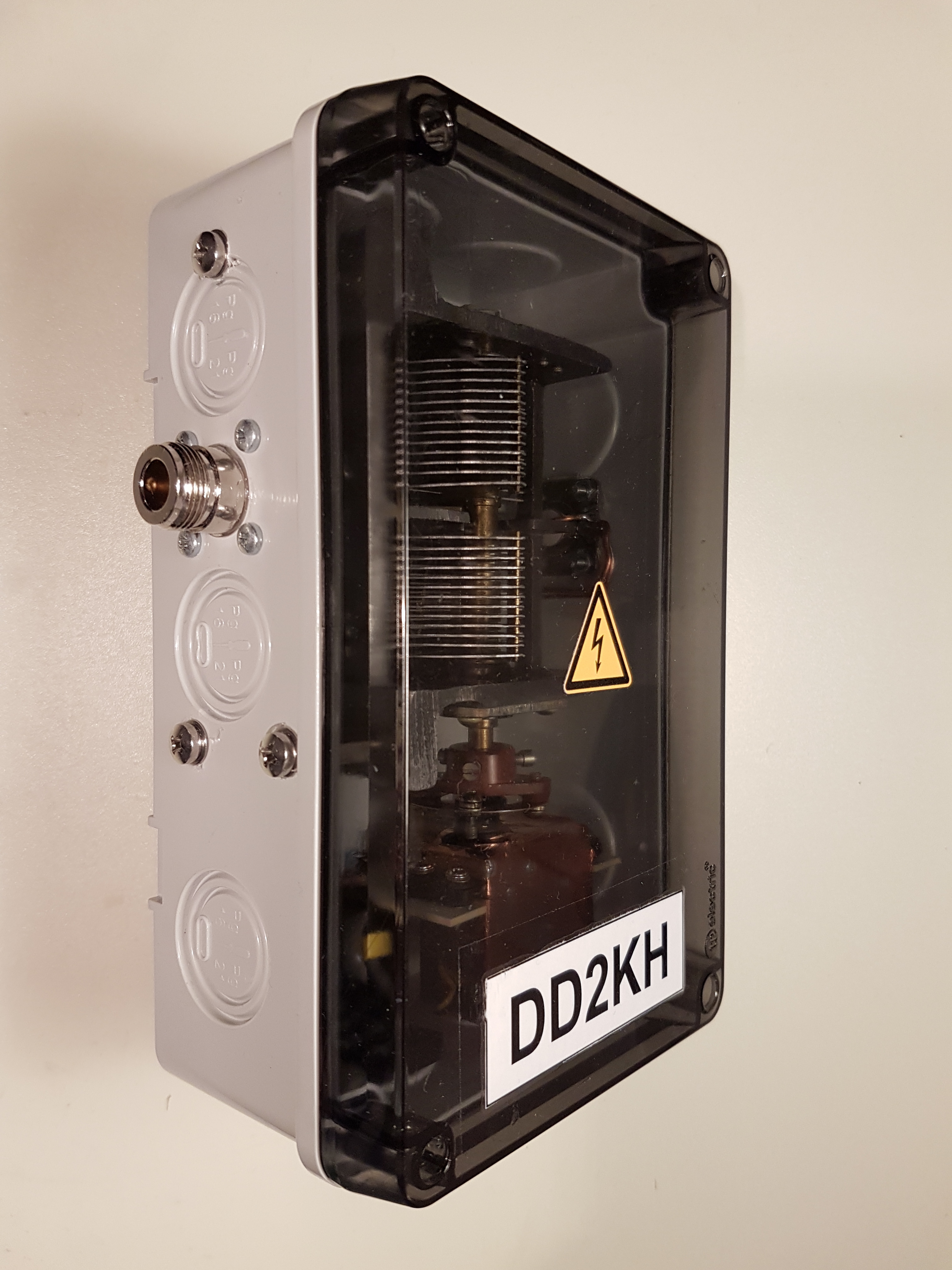
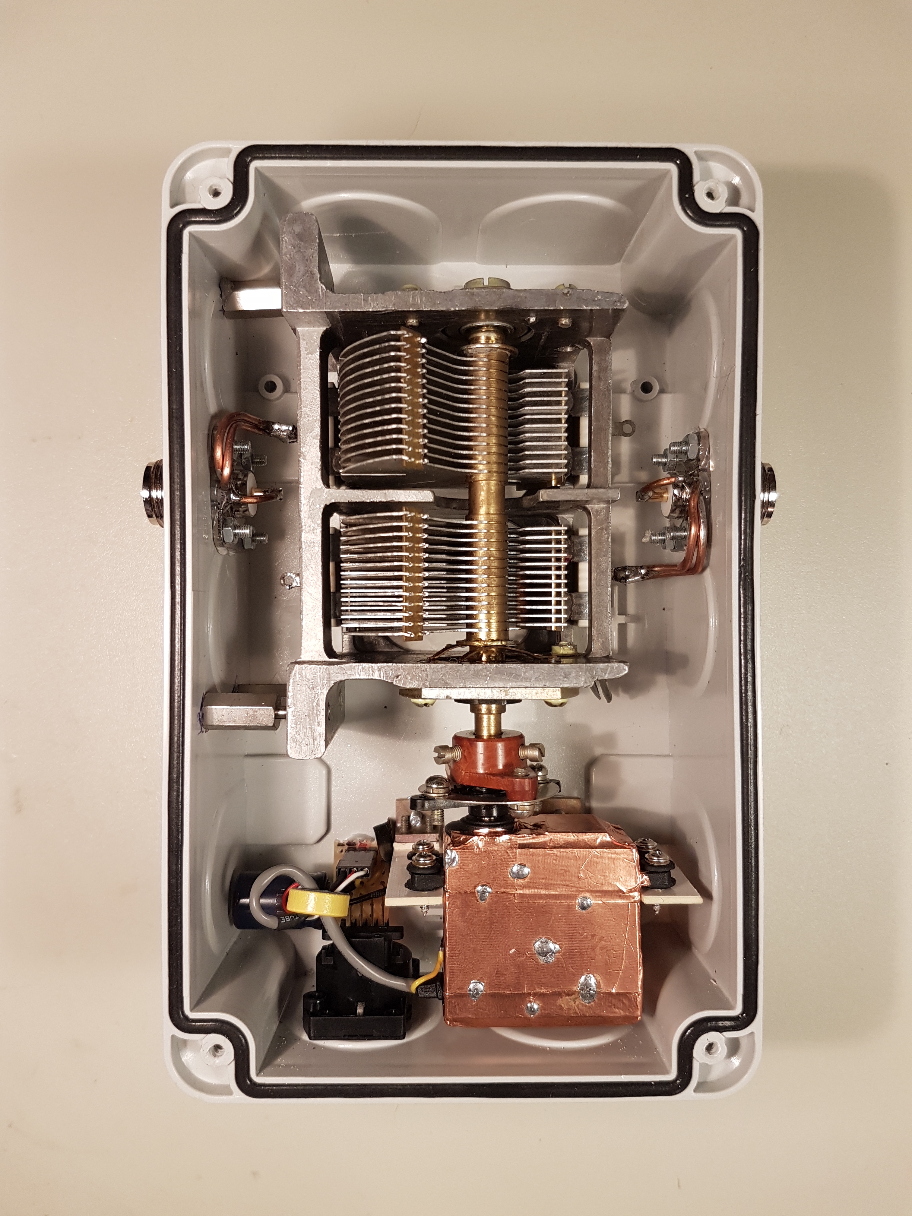
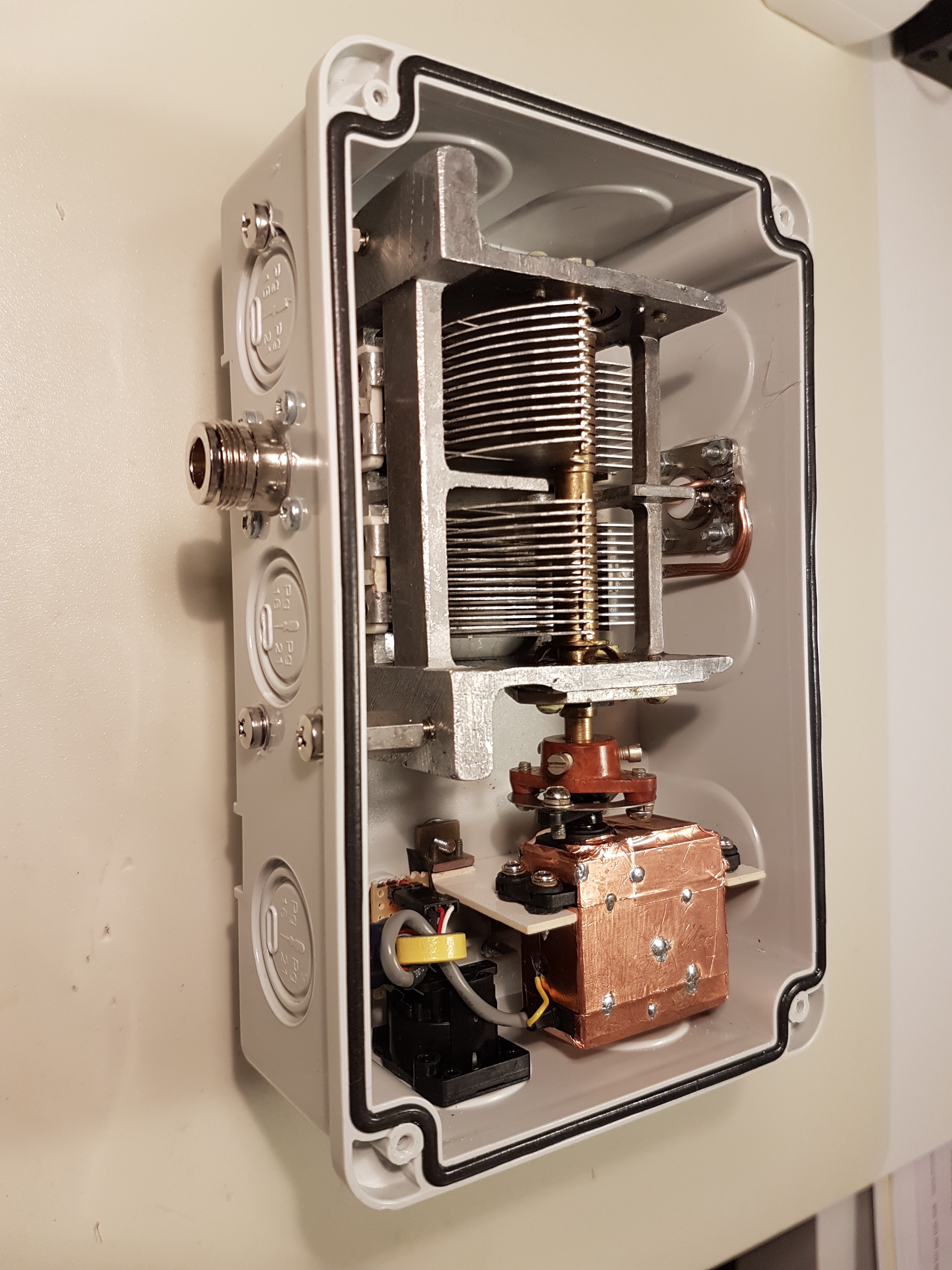
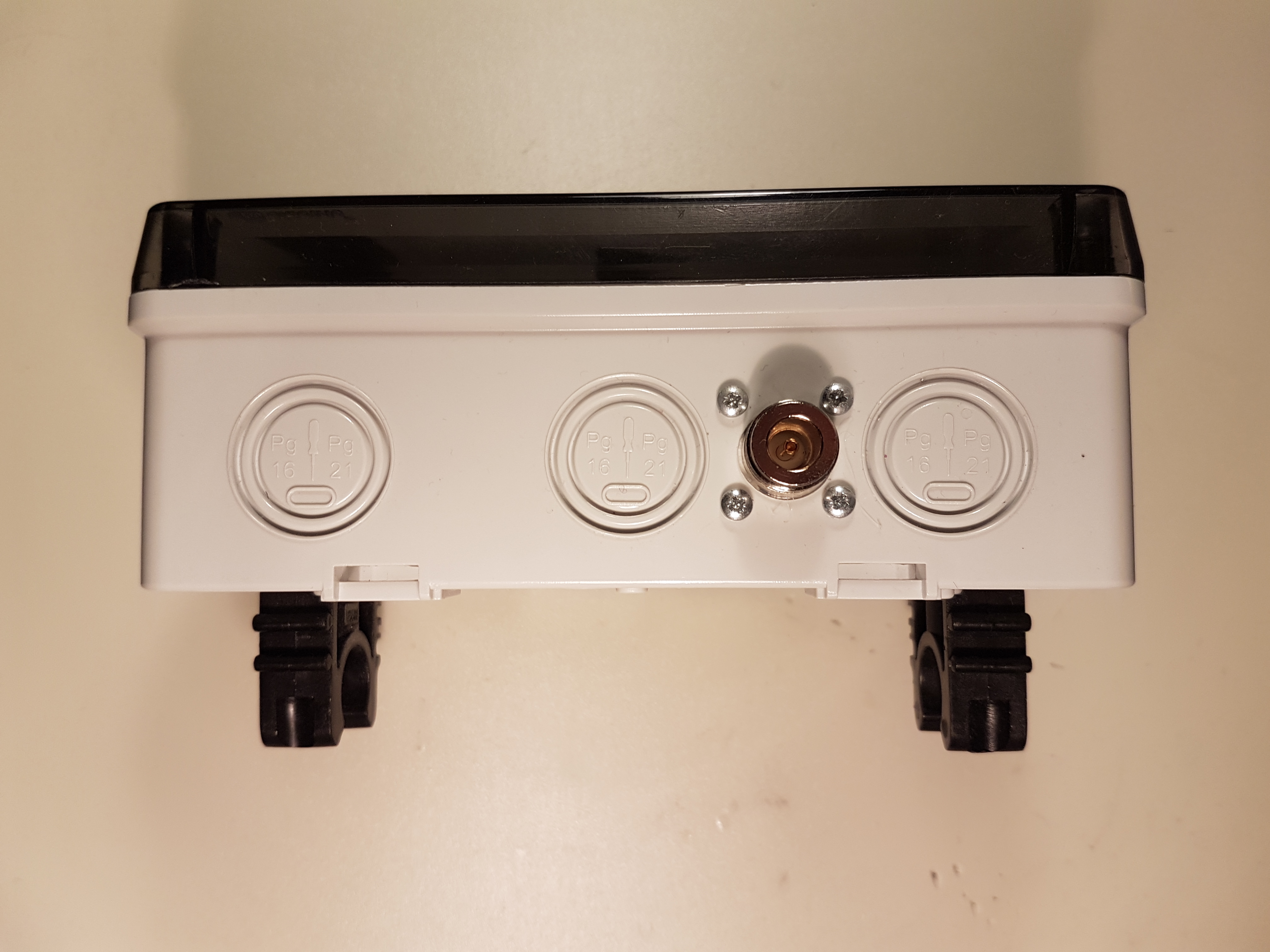
The main loop is connected to the capacitor box using Type-N connectors. These connectors have been chosen because of their water-proof nature. The centre pin has been connected to the body of the connector in order to ensure that both inner conductor and shield of the main loop coax cable are connected. In order to minimise resistive losses, each side of the capacitor is connected to the corresponding N-connectors using two solid copper wires.
The capacitor consists of two 14 pF .. 450 pF variable capacitors connected in series through the common rotor shaft. Each of the two capacitor’s stators is connected to one end of the main loop. Due to the rotors being connected togethr through their common shaft, there is no need to use any lossy wiper contact to connect the main loop to the capacitor’s rotor.
In order to protect it from RF interference, the RC servo has been completely wrapped in adhesive copper foil and its signal wire has been replaced with a coaxial audio cable. A common-mode choke around the signal wire prevents the RF interference from entering the servo. The servo has been mounted on a bracket made out of a piece of circuit board and some angled brackets that came along with the capacitor. The connection between the servo and capacitor shafts has been accomplished using the mounting hardware that came along with both devices.
A heavy-duty RJ45 connector has been mounted towards the bottom of the enclosure, it is soldered to a small stripboard PCB that holds a large electrolytic capacitor and the pin header for connecting the servo cable.
The capacitor box is firmly secured to the antenna mast using 20 mm plastic pipe brackets.
Control Unit
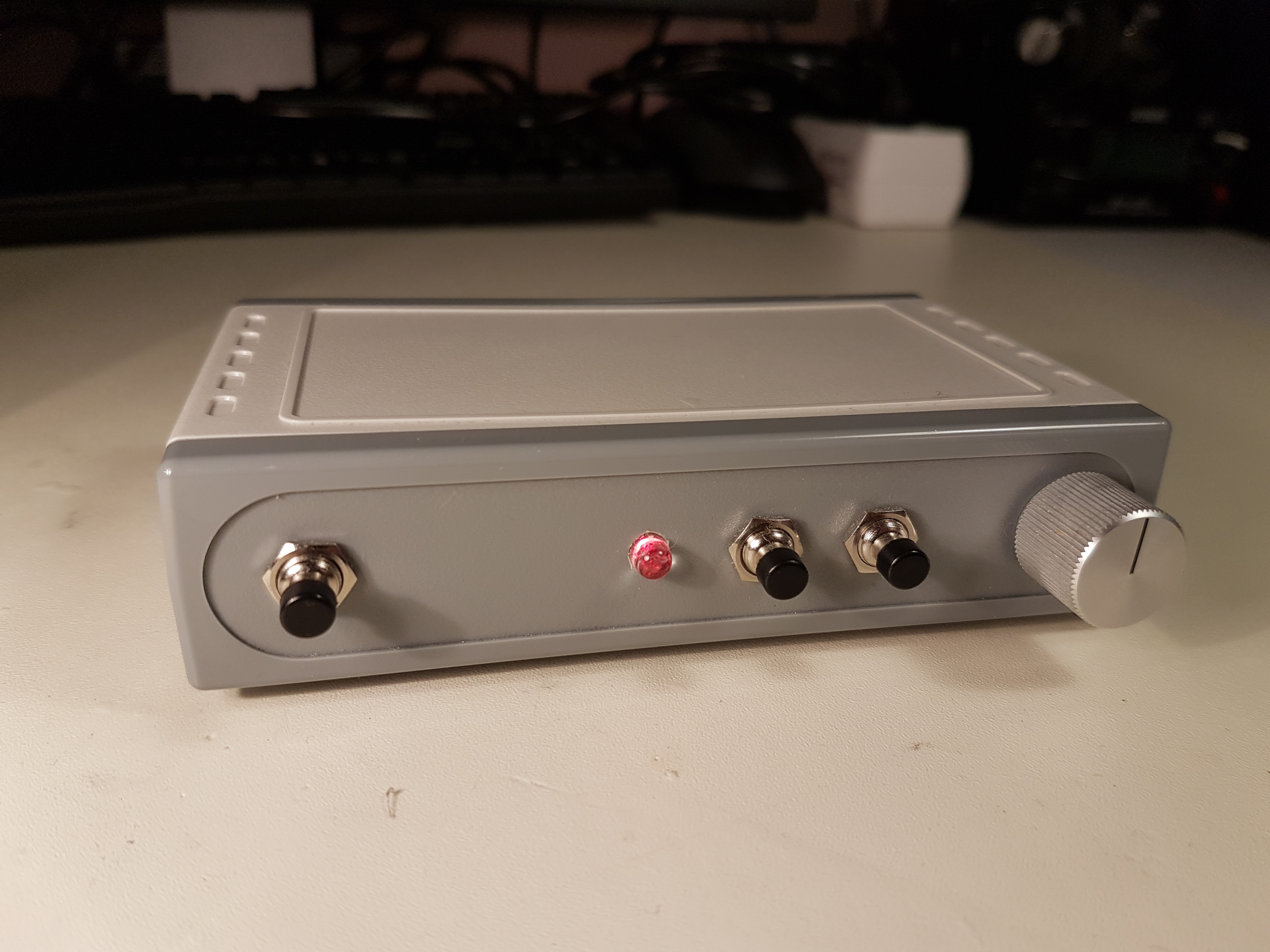
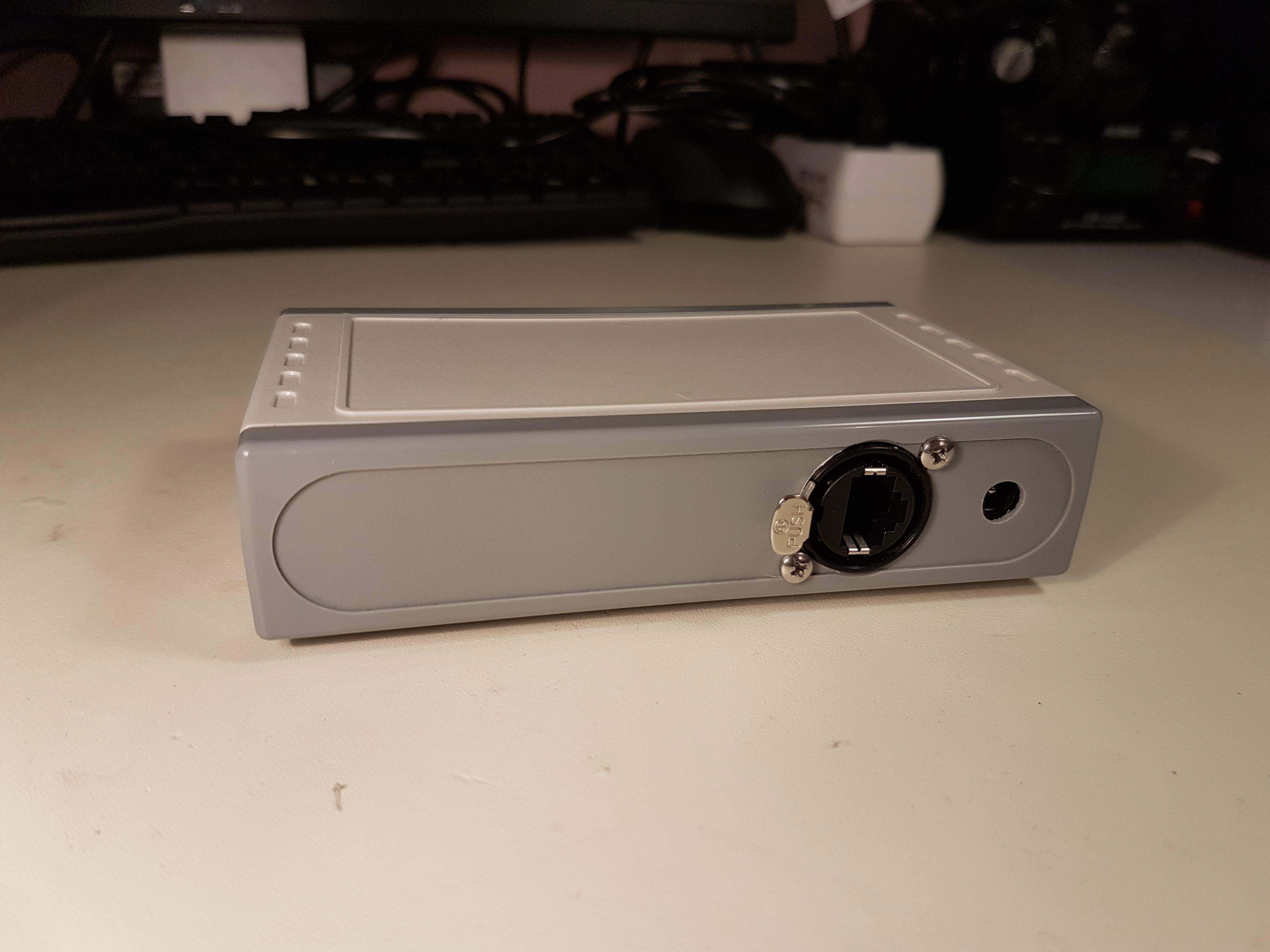
The following pictures show the details of the control unit. It has been built around an off-the-shelf enclosure of type “RND 455-00119” having the dimensions of 130 x 76 x 30 mm. It has a relatively small form factor and nicely fits on top of a Yaesu FT-891 transceiver. The front panel holds a power button (from left), a status LED, increase/decrease buttons and a fine-tuning potentiometer. The back panel holds a heavy-duty RJ45 connector and a 12 V DC power jack for charging the battery pack located inside.
Battery power was chosen because the system consumes very little power and can run for weeks on a single battery charge. The increased weight due to the batteries gives the device more stability and prevents it from sliding around when pressing the buttons. Further, removing the need for a power cable simplifies the setup and avoids a potential source of interference.
In order to mitigate malfunctions due to RF interference, the whole inside of the enclosure has been covered in adhesive copper foil that is connected to the power supply ground.
In order to protect the internals from damage due to electrostatic discharge (ESD), the metal bodies of the push-buttons and potentiometers have been connected to the power supply ground ground. This ensures that an ESD spark would first hit the metal bodies of the control elements, which are the shortest path towards ground.
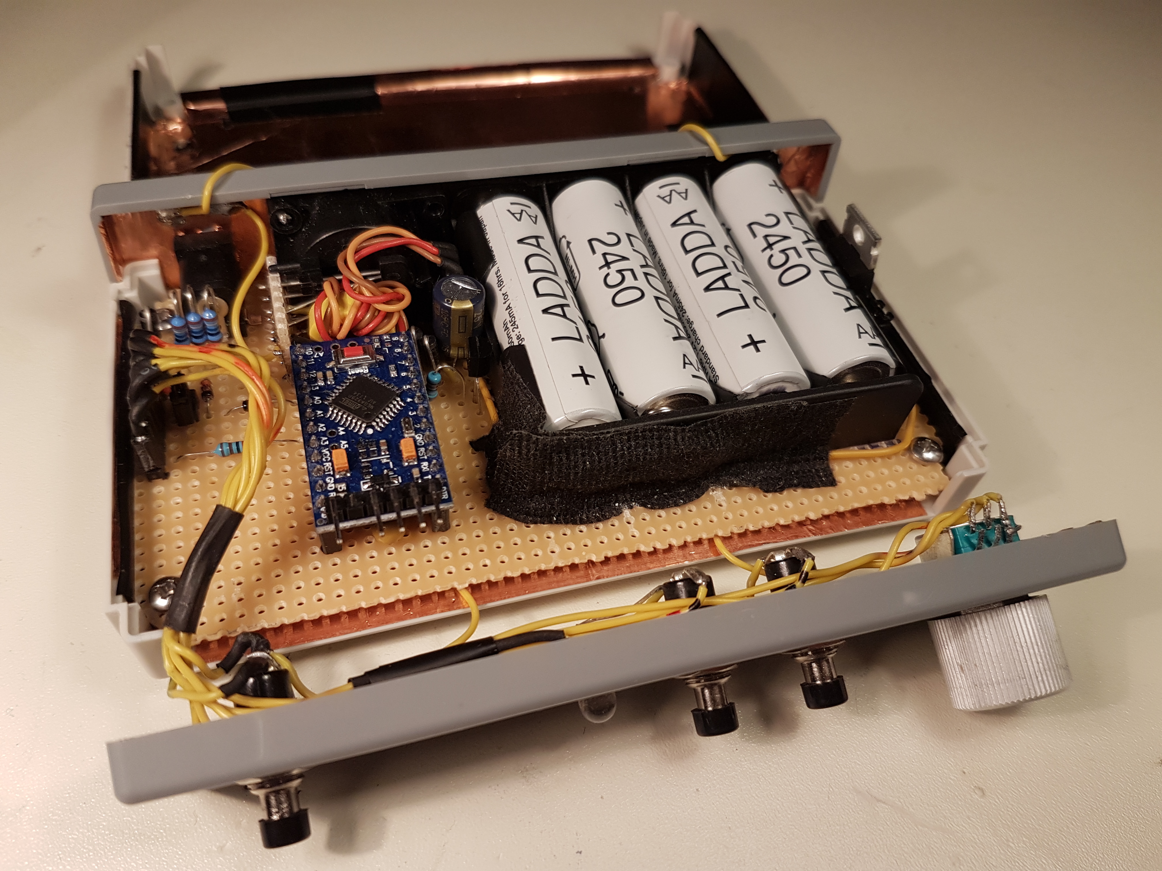
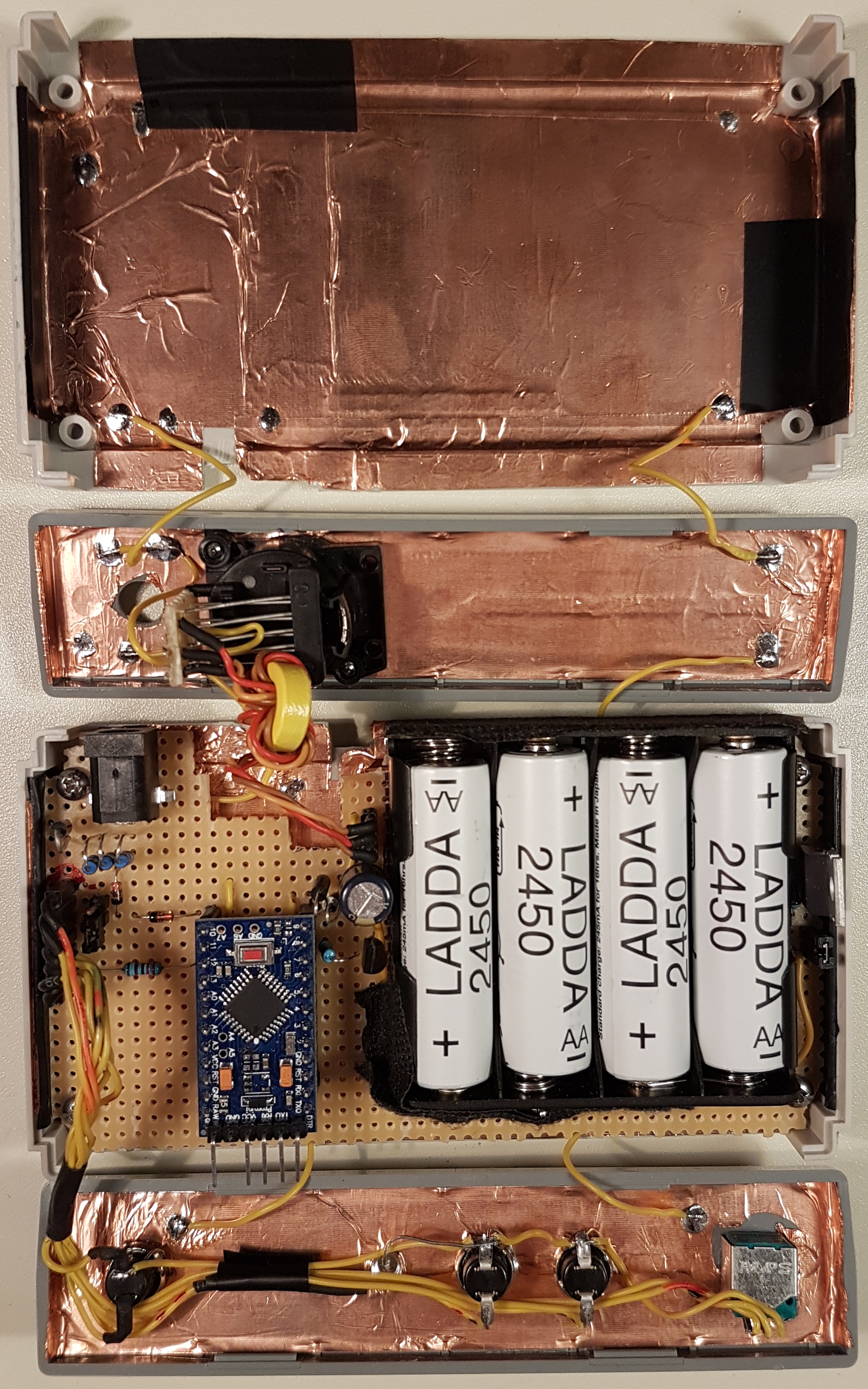
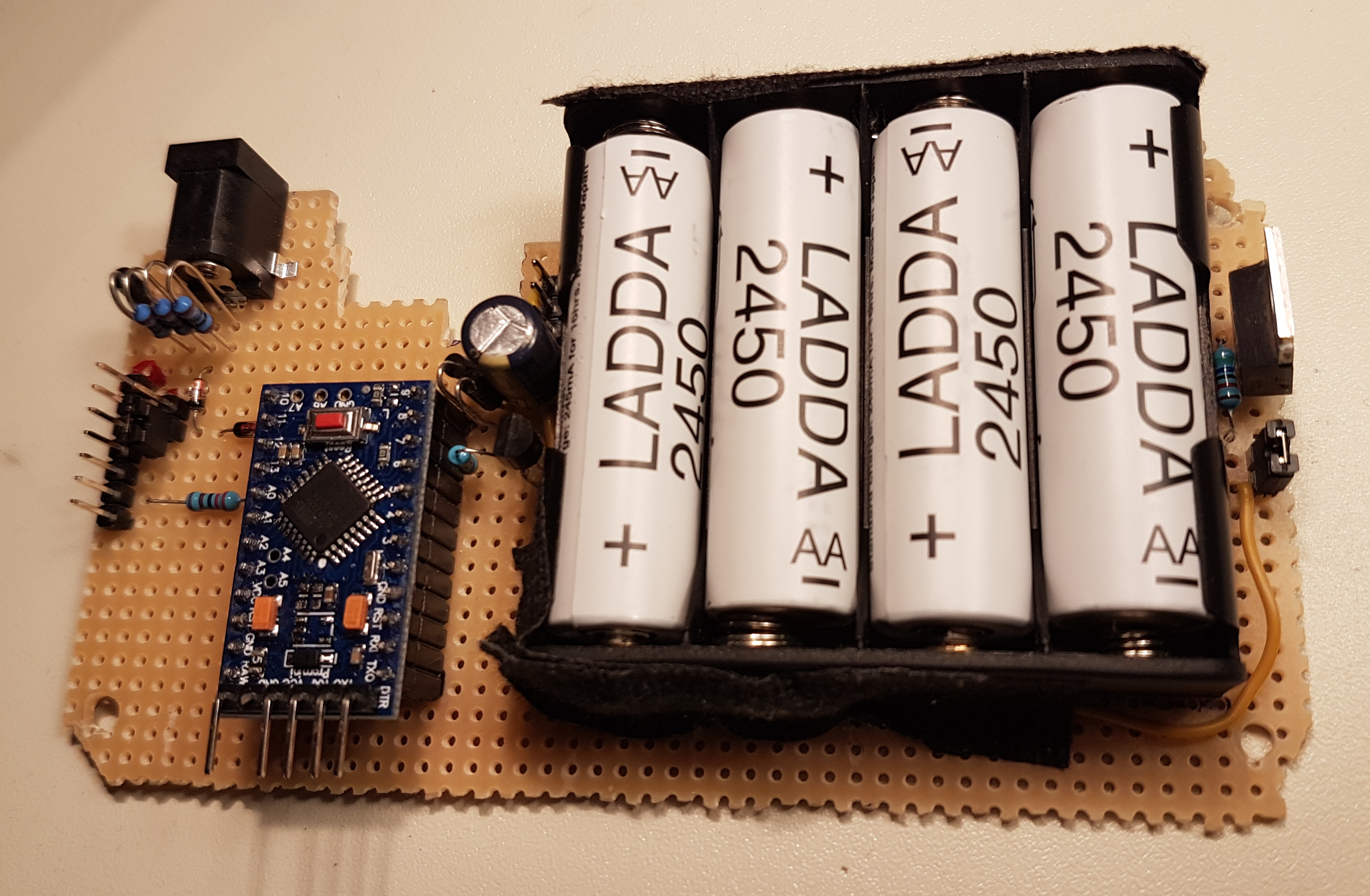
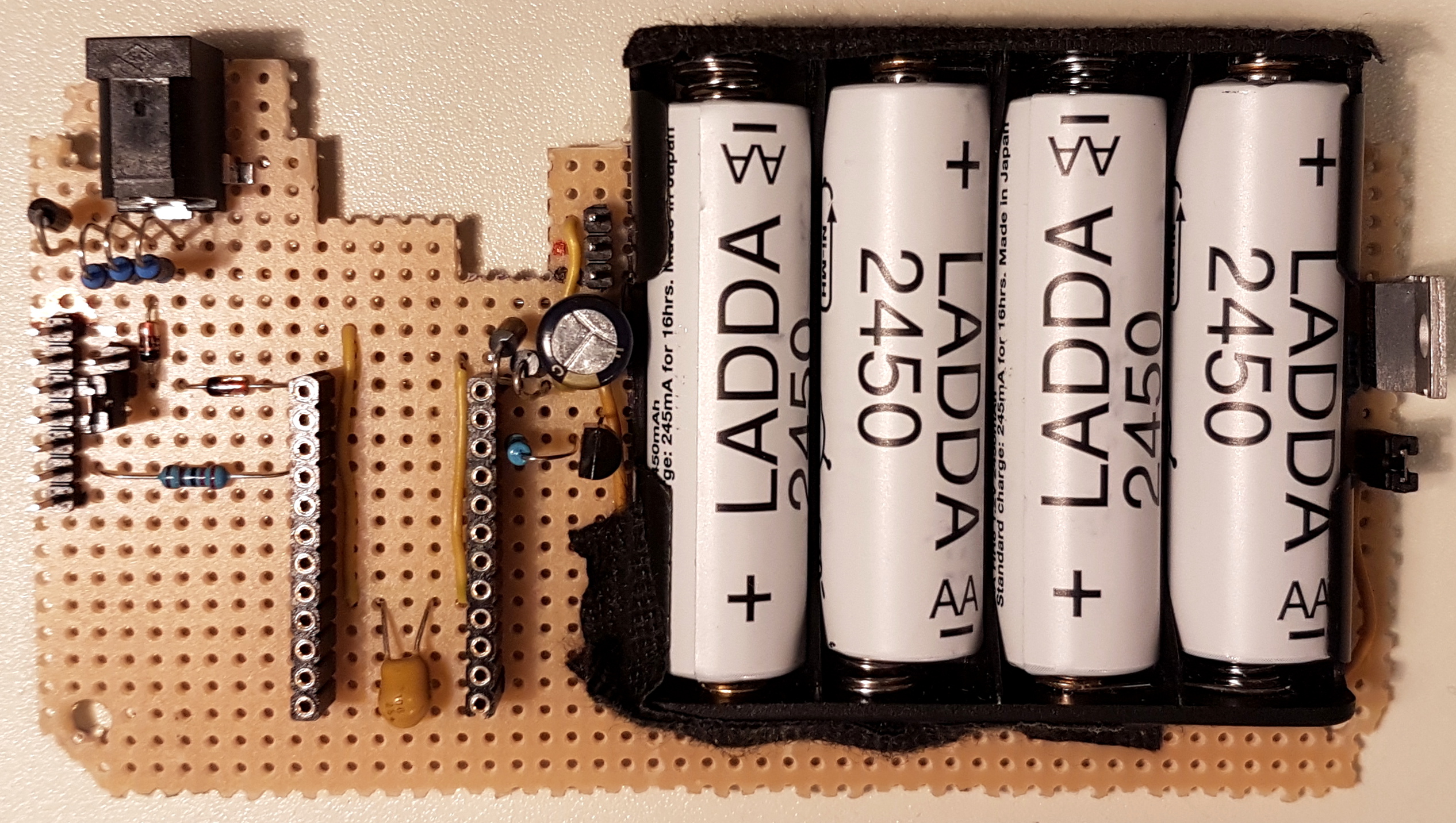
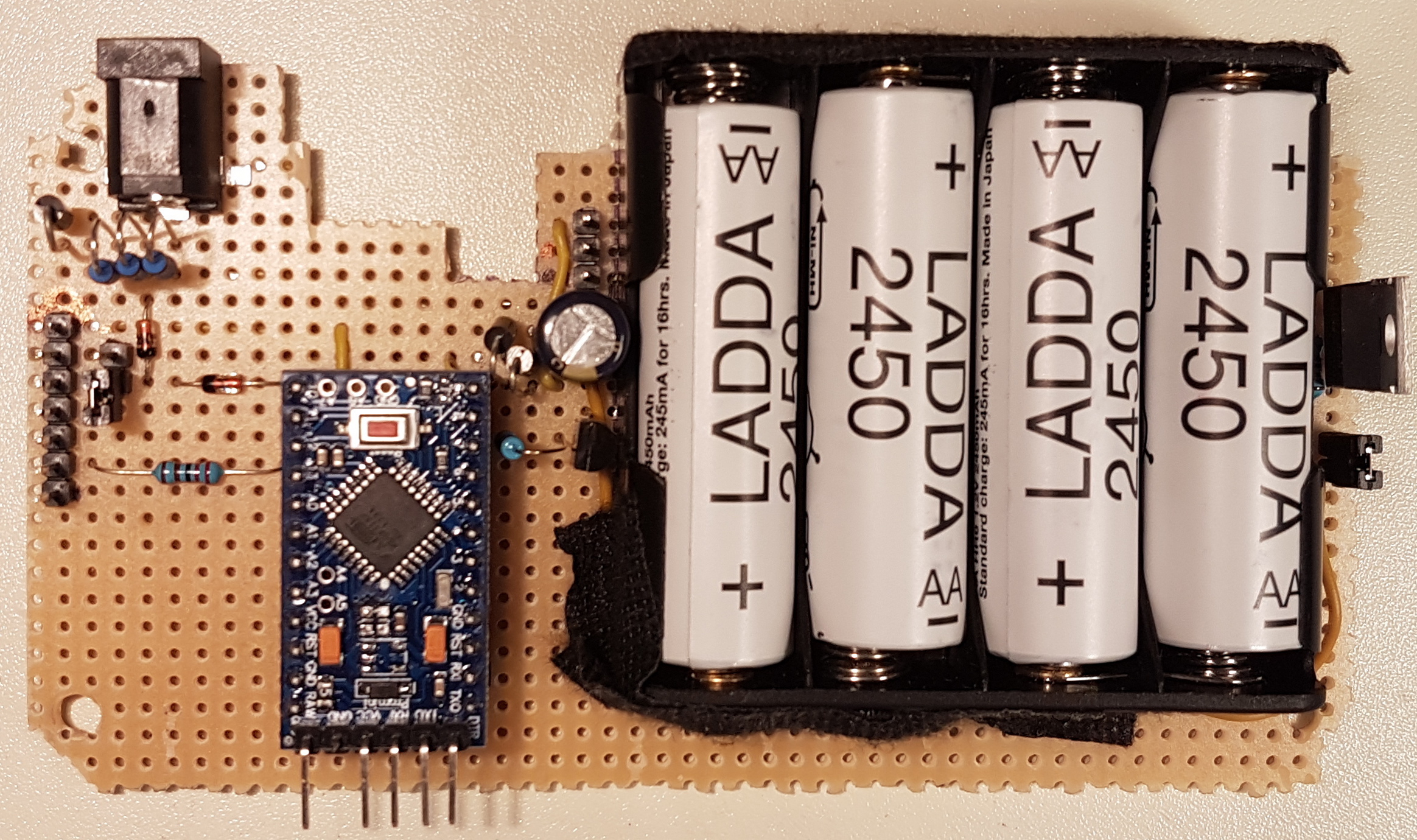
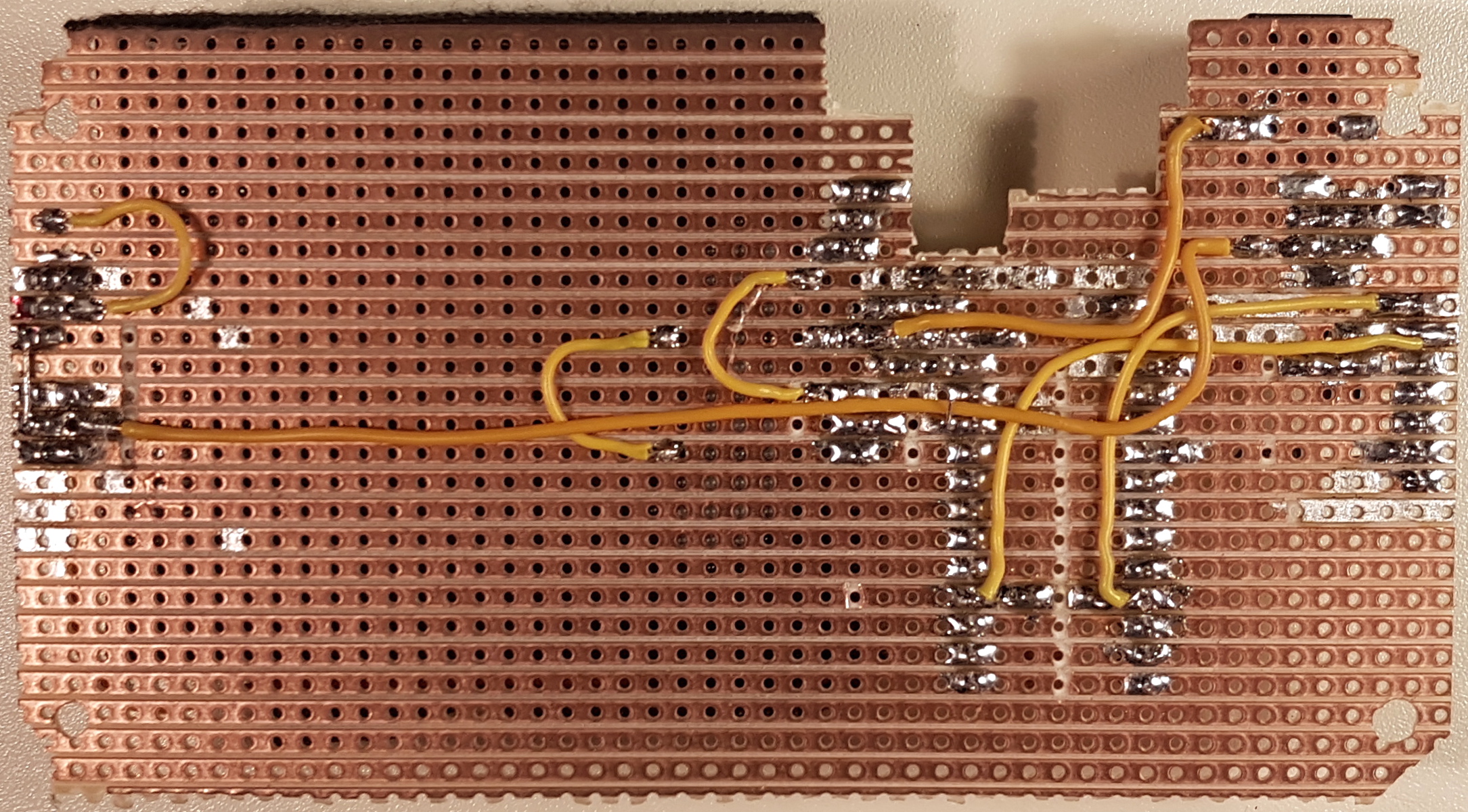
The internal components have been mounted on a stripboard PCB whose top and bottom layouts are shown in the above pictures. One can see the battery pack along with the Arduino Pro Mini board, power jack and other components. A recession has been carved into the PCB in order to accommodate for the bulky RJ45 connector.
A common-mode choke along the wires coming from the RJ45 connector prevents any RF interference from entering the circuit.
Circuit Diagram
The following picture shows the schematic of the magnetic loop antenna tuner system.
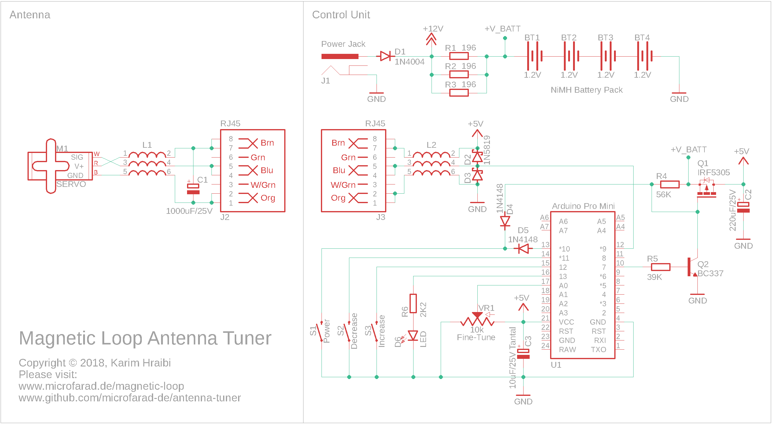
Besides the Arduino board U1, the schematic contains the the blocks listed down below.
Battery charger (D1, R1 to R3, BT1 to BT4): this is a simple circuit for charging the battery pack consisting of 4 NiMH cells. The diode D1 is needed for inverse polarity protection. Resistors R1 to R3 are current-limiting resistors, 1/4 Watt resistors have been used, thus we need three of them in parallel in order to dissipate the resulting thermal energy.
Soft power switch (S1, Q1, Q2, D4, D5, R4, R5): a soft power switch has been implemented in order to enable the auto power-off feature. When S1 is depressed, the gate pin of the field-effect transistor (FET) Q1 is pulled to ground via D4. Q1 becomes conducive and connects the V_BATT terminal to the +5V rail which powers-up the Arduino board. Once booted, the Arduino senses the signal from the power switch on digital input pin 10 (connected via D5). If S1 has been pressed long enough, the Arduino would power-up the NPN transistor Q2 via the digital output pin 7, which in turn will keep the gate of Q1 constantly connected to ground. Q1 will stay conductive even after S1 gets released, as long as the digital output pin 7 is set to high. The Arduino can power down the system anytime by setting digital output pin 7 to low, thus switching off Q2 and Q1. In theory the Arduino could directly drive the gate of the FET Q1 without using Q2 as a buffer; however this would result in approximately 500 µA of idle current constantly flowing through R4 into pin 7 while the system is turned off.
Note: the IRF5305 MOSFET Q1 is over-dimensioned for its task. A logic level p-channel MOSFET such as the IRLML2244 would be a better choice as it has a smaller form factor, a lower gate threshold voltage  and a lower corresponding drain-to-source on-resistance
  .
.
Human interface (S1 to S3, VR1 and D6): the human interface consists of three push-buttons (S1, S2, S3) a potentiometer (VR1) and a status LED (D6). When pressed, the push-buttons would connect the respective Arduino digital input pins (10, 11, 12) to ground. When the push-buttons are released, the digital pins are connected to +5V via internal pull-up resistors inside of the Arduino’s ATmega microcontroller. Digital output pin 13 drives the LED D6 via the R6 current-limiting resistor. The fine-tuning potentiometer VR1 has its wiper connected to Arduino’s analog pin A0. In order to minimize noise sensitivity, the end terminals of the potentiometer need to be connected as close as possible to the VCC and GND power inputs of the Arduino.
Servo signal transmission line (C1, L1, L2, J2, J3, D2, D3): the signal to RC servo which is located within the capacitor box the antenna side is transmitted via an 10 meter shielded Ethernet cable. In order to reduce the line resistance, each of the positive, negative and signal lines use a pair of the Ethernet cable’s wires connected in parallel. The pulse-position modulation (PPM) signal for driving the servo is generated by Arduino’s digital output pin 9. The 1000 µF capacitor C1 is required for accommodating the current ripples produced by the Servo. The common-mode chokes L1 and L2 are required for suppressing the electromagnetic and RF interference produced by the transmitting antenna. The Schottky diodes D2 and D3 protect the Arduino’s input from accidental high voltage ingress due to electrostatic discharge.
Capacitors C2 and C3 smoothen any power supply voltage ripples caused by the servo and other sources of interference.
Downloads
Below you can find GitHub download links for the Arduino firmware source code, User Manual, Eagle schematic and bill of material. All of the source code is distributed under the GNU General Public License v3.0 and is free.
Please note that the current implementation uses the watchdog timer functionality which requires the customized Arduino bootloader found under the link below. For more details, please follow the installation instructions found within the README file on GitHub.
Antenna Tuner Control Unit Firmware
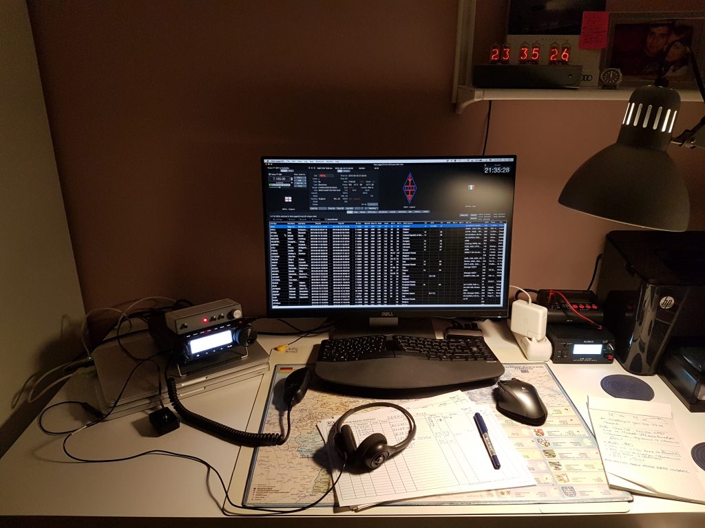
Appendix: Mobile Radio Shack
The magnetic loop antenna that is described on this page is part of the mobile radio shack described below. This amateur radio shack belongs to the call sign DD2KH. More information about the callsign can be found on QRZ.com under the following link: www.qrz.com/db/DD2KH.
The amateur radio shack consist of:
- antenna: DIY magnetic loop
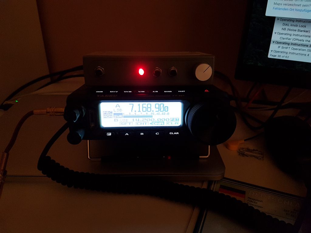
- transceiver: Yaesu FT-891
- battery: LiFePO4 12 Ah
- power supply: Alinco DM-430-E (30 A)
- Tx power: 100 W (SSB)
Following are some pictures of the radio shack.