Following is the example application of an Arduino running on battery power with minimal current consumption. It features a soft power on circuit that enables the Arduino to power off itself. The lowest current consumption is around 10 μA and enables the device to run for thousands of hours on a single CR2025 Lithium coin cell.
Described is a “Little Fish” kids toothbrush timer has been implemented using a 3.3 V / 8 MHz Arduino Pro Mini compatible board. This project showcases the following applications for the Arduino:
- Minimum power consumption through the extensive use of the ATmega328P sleep modes
- Random number generation
- Soft power on circuit
Table of Contents
Theory of Operation
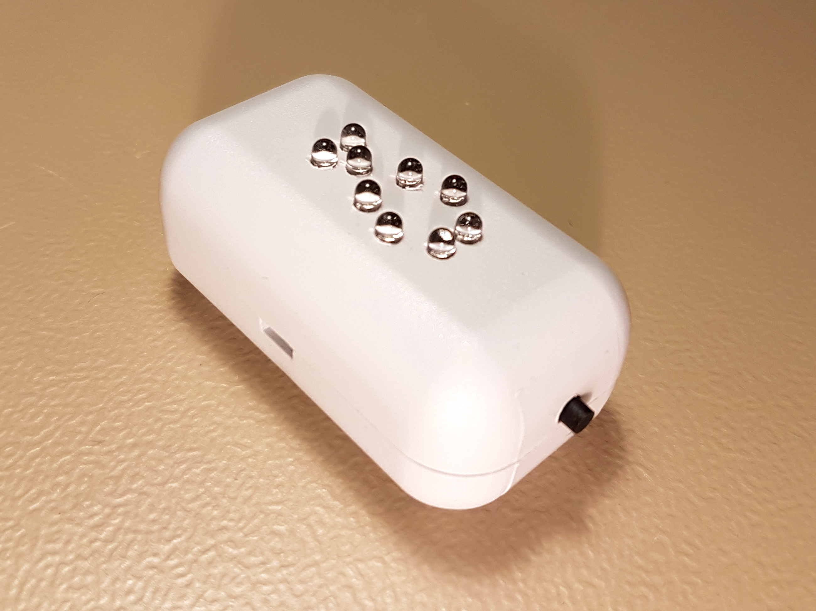
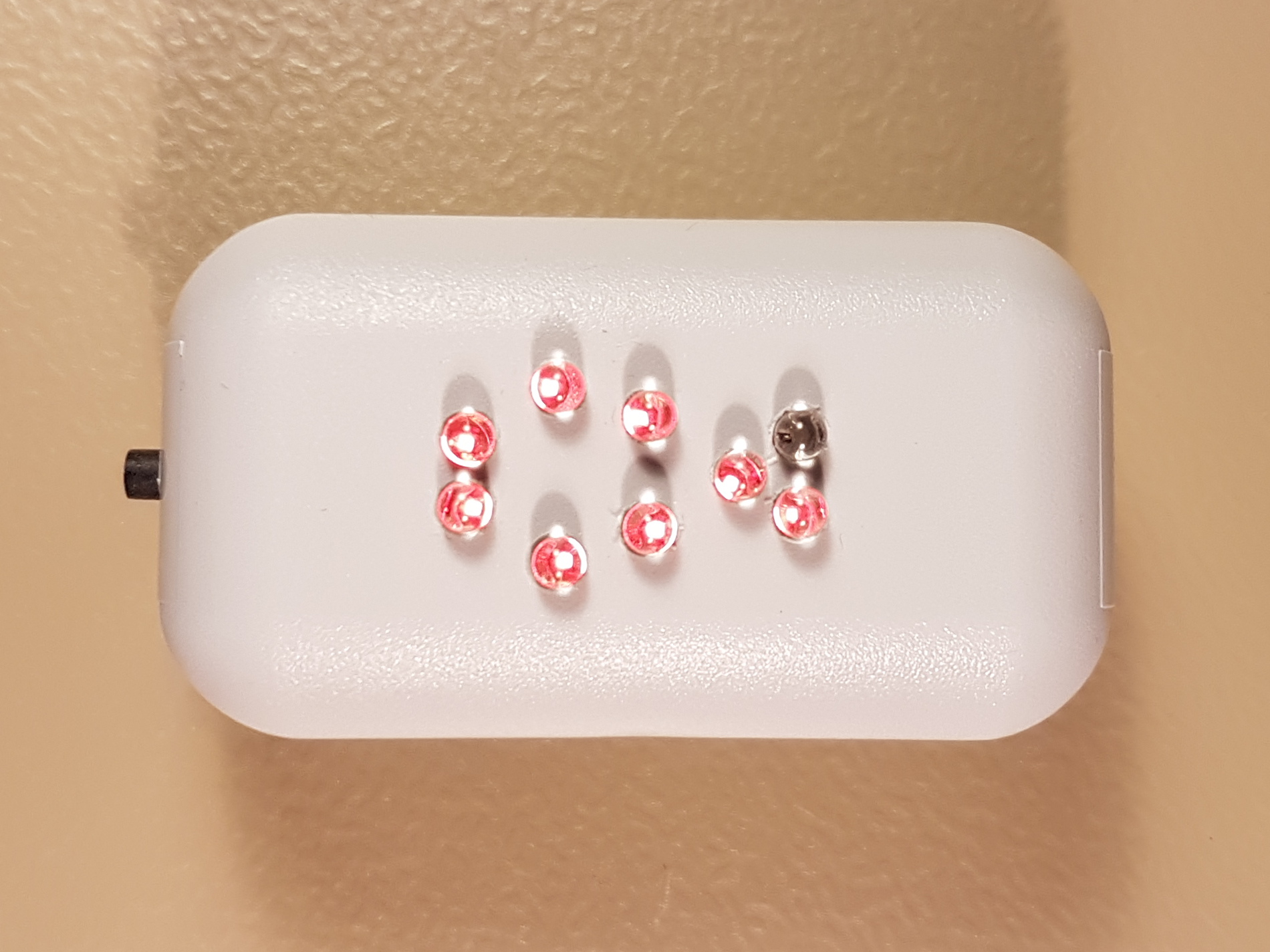
The device features 9 LEDs arranged in a “little fish” pattern. When turned on, the eyes of the fish will start to blink once per second. More and more LEDs begin to blink as time passes. One of several random animation sequences is activated as soon as the recommended two minute tooth brushing duration elapses, then the system will power itself off.
The device implements a soft power on circuit using a tactile switch and two FET transistors. Briefly pressing the power button will power up the system and initiate the timer sequence. Pressing the power button during approximately 2 seconds while the device is on will skip the timer sequence and directly activate the LED animation sequence prior to powering down the system.
The device is designed to consume a very low current and is able to run on a single CR2025 or similar 3 V Lithium cell for thousands of cycles. The current consumption is around 10 μA during the Power-Down sleep phase and around 1.2 mA when all the LEDs are on. The device consumes no current when the power is off.
In order to reduce the bill of material, all 9 LEDs share one common dropper resistor. Turning on multiple LEDs simultaneously is not recommended as it will result in some of the LEDs glowing brighter than others. A multiplexing routine is used for sequentially turning on one of the LEDs at a time and doing this fast enough to create the illusion that they are simultaneously lit due to the persistence of the human vision.
The device uses a random number generator for selecting the different animation sequences using Arduino’s built-in random() function.
This sketch has been implemented and tested on an ATmega328P based Arduino Pro Mini compatible board running on 3.3 V / 8 MHz.
It is recommended to activate the watchdog support on the Arduino bootloader by defining the WATCHDOG_MODS macro. This will reduce the bootloader’s power-up delay, thus invalidating the need to hold the power button for around 2 seconds for the system to turn on. Please download the bootloader and follow the installation instructions from the following GitHub repository: https://github.com/microfarad-de/bootloader.
Arduino’s onbard 3.3 V linear regulator as well as the power LED need to be unsoldered as they would otherwise significantly increase the overall power consumption. A good tutorial for removing both components can be found under https://www.iot-experiments.com/arduino-pro-mini-power-consumption.
The following video shows the toothbrush timer in action. Please note that the fast LED flickering is not visible in real life and is due to the multiplexing interacting with the video frame rate.
Further detailed documentation can be found within the comments of the Arduino source code that can be downloaded at the bottom of this article.
Mechanical Design
The device is built around an off-the-shelf plastic enclosure of type “TEKO 10006” having the dimensions of 56 x 31 x 24 mm. Holes have been drilled for the nine 3 mm LEDs and the tactile power switch.
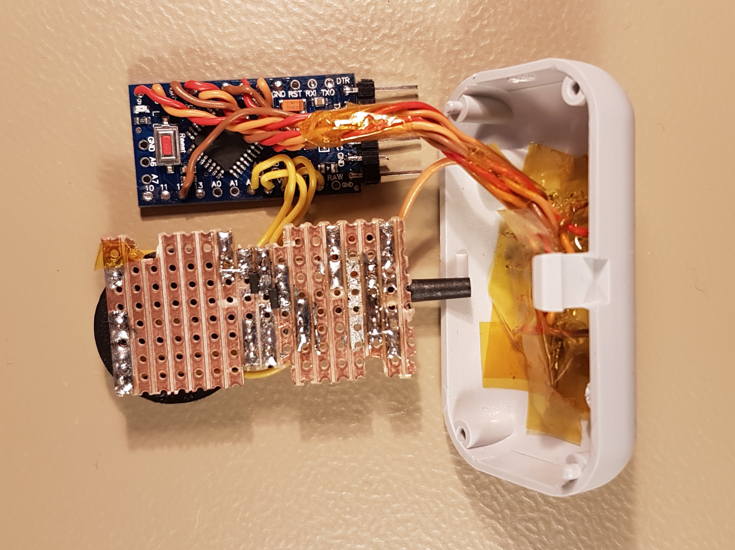
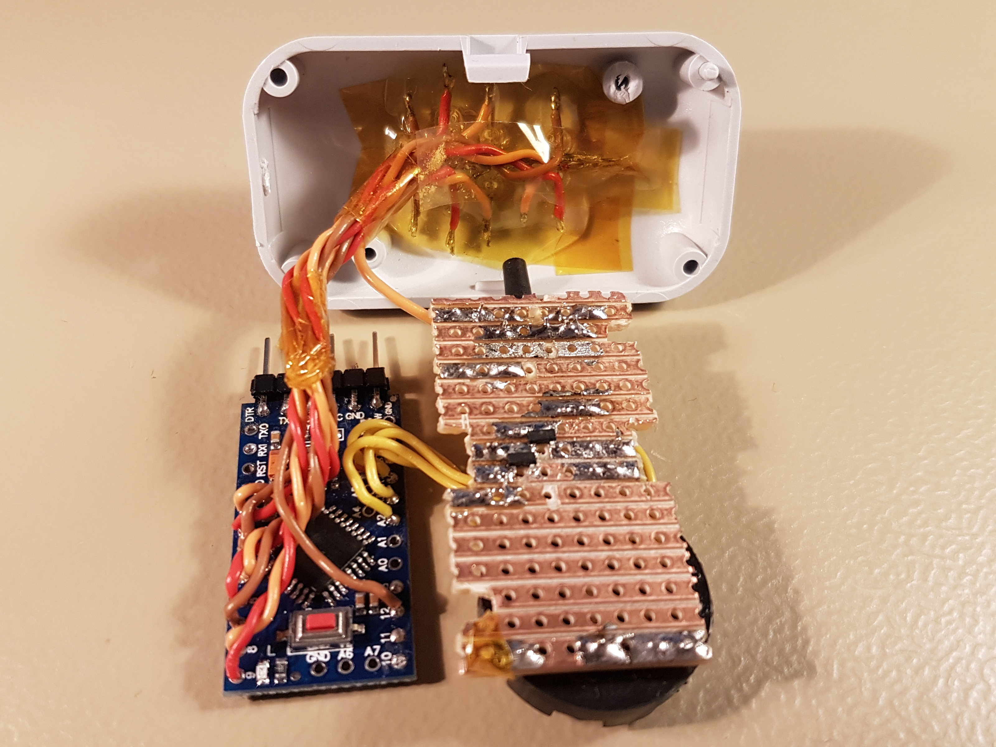
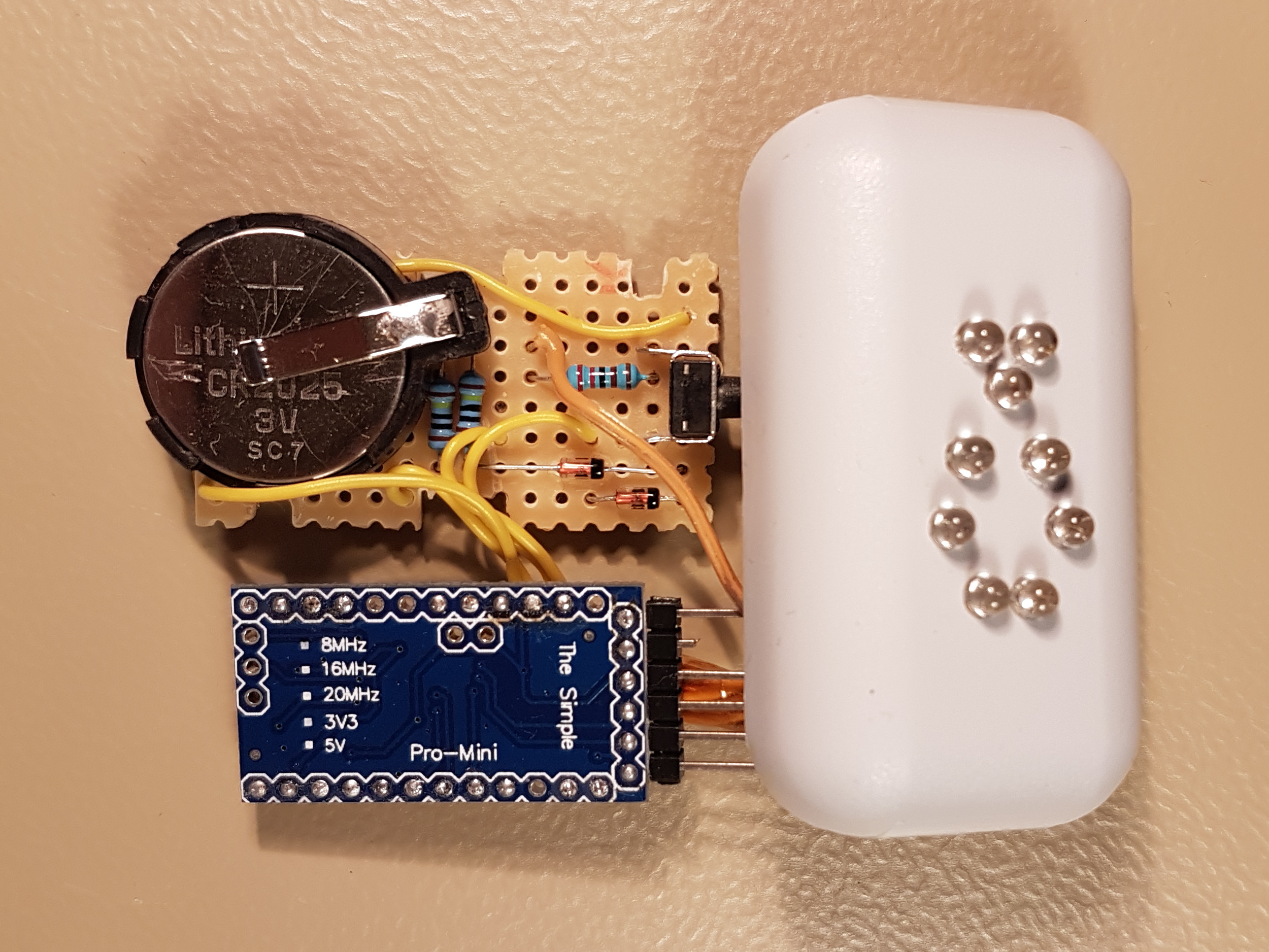
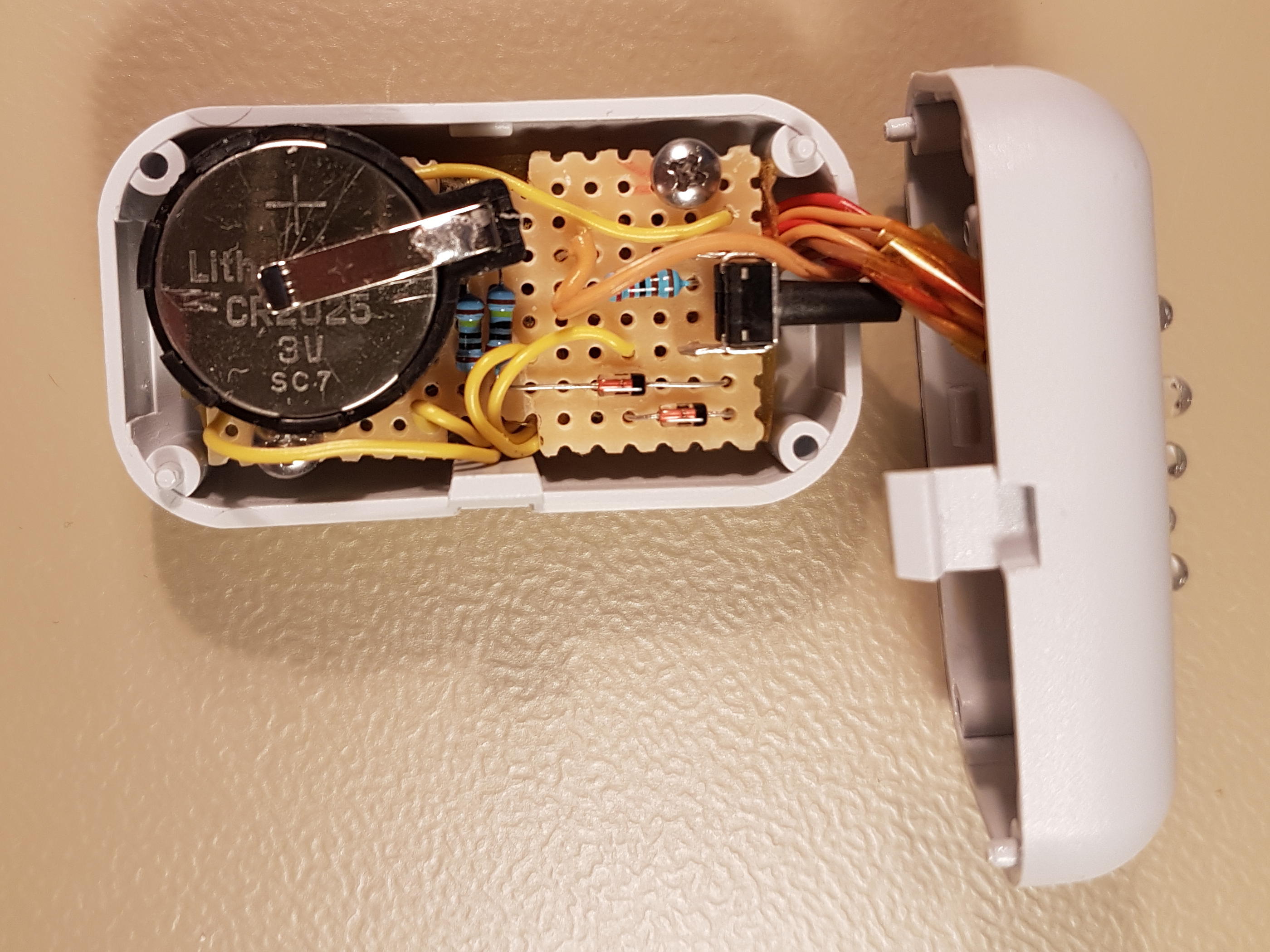
The CR2025 battery holder, tactile switch, LED dropper resistor and the soft power on circuit have been mounted on a stripboard PCB that has been screwed into place inside the enclosure. The Arduino board has been tucked behind the main PCB. The 9 LEDs are held by friction inside their holes. Wires have been directly soldered to the LED terminals, connecting them to the corresponding Arduino’s digital input pins and the main PCB. Kapton tape has been used for isolating the LED connections and the underside of the main PCB.
The pictures below show the insides of the toothbrush timer in more detail.
Power Saving
The typical microcontroller (MCU) power saving strategy consists of powering off as many hardware resources as possible at any given point in time and only enabling the central processing unit (CPU) clock when processing work is actually required. Thus, the CPU shall be put to sleep during most of the time and only wake up for very brief periods of time. On an ATmega328P (and similar MCUs), triggering any of the available hardware interrupts will cause the CPU to wake up.
Different sleep modes are available for the ATmega328P MCU. Each of them disables a different set of hardware peripherals which will consequently reduce the overall power consumption. The following table shows the available sleep modes (source: ATmega328P Datasheet Section 14.2).
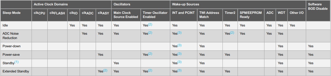
Being interested in disabling as many hardware resources as possible at any given point in time, we would like to keep the Arduino in the Power-Down mode as often as possible. Power-Down being the sleep mode with the least power consumption. However, in the current application we would sometimes need to resort to the Idle mode which would enable the clkIO hardware that is required for running the Timer/Counter 0 (TC0). TC0 is being used for generating the millisecond interrupt needed by Arduino’s millis() function of which we make extensive use for time duration measurements within our code.
Further, any unused hardware peripherals can be permanently disabled during initialization time irrespective of whether a sleep mode has been a enabled. This is being achieved by adding the following code into the Arduino initialization function.
#include <avr/sleep.h>
#include <avr/power.h>

/*
 * Arduino Initialization Routine
 */
void setup () {
  ADCSRA &= ~_BV(ADEN);    // Disable the ADC (this needs to be done first, otherwise the ADC will consume power!
                           // See ATmega328P datasheet Section 28.9.2)
  power_all_disable ();    // Turn off all hardware peripherals
  power_timer0_enable ();  // Turn on Timer 0 is used for generating the millisecond interrupt for the millis() function

  /*
   * Enable watchdog interrupt with a 1 second interval.
   * The watchdog interrupt will wake-up the CPU from deep sleep once per second
   * and will serve as the main clock source for timekeeping.
   * Please refer to the ATmega328P datasheet 15.9.2. "WDTCSR – Watchdog Timer Control Register"
   * for more information about configuring the WDT control register.
   */
  cli ();
  WDTCSR |= _BV(WDCE) | _BV(WDE);
  WDTCSR = _BV(WDIE) | _BV(WDP2) | _BV(WDP1);
  sei ();
}

/*
 * Watchdog Interrupt Service Routine
 */
ISR (WDT_vect)  {
  // Do nothing
}
In particular, we have disabled all of the hardware peripherals except for Timer/Counter 0. Additionally, the above code configures the Watchdog Timer Interrupt (WDT) to be triggered once in every second. This ensures that the MCU is periodically waken up from the Power-Down mode, as the WDT stays active during any of the available sleep modes.
Entering the Idle and Power-Down sleep modes is achieved by calling one of the following two functions from within the Arduino main loop.
#include <avr/sleep.h>

/*
 * Send the CPU Into the Idle Sleep Mode
 * The CPU will be waken-up within 1 millisecond by the Timer 0 millis() interrupt.
 * Please refer to ATmega328P datasheet Section 14.2. "Sleep Modes" for more
 * information about the different sleep modes.
 */
void lightSleep () {
  set_sleep_mode (SLEEP_MODE_IDLE);  // Configure lowest sleep mode that keeps clk_IO for Timer 0
  cli ();                            // Disable interrupts
  sleep_enable ();                   // Prepare for sleep
  sei ();                            // Enable interrupts
  sleep_cpu ();                      // Send the CPU into sleep mode
  sleep_disable ();                  // CPU will wake-up here
}

/*
 * Send the CPU Into the Power-Down Sleep Mode
 * The CPU will be waken-up within 1 second by the watchdog interrupt.
 * Please refer to ATmega328P datasheet Section 14.2. "Sleep Modes" for more
 * information about the different sleep modes.
 */
void deepSleep () {
  set_sleep_mode (SLEEP_MODE_PWR_DOWN);  // Configure lowest possible sleep mode
  cli ();                                // Disable interrupts
  sleep_enable ();                       // Prepare for sleep
  sleep_bod_disable ();                  // Disable brown-out detection (BOD) (not possible in SLEEP_IDLE_MODE)
  sei ();                                // Enable interrupts
  sleep_cpu ();                          // Send the CPU into sleep mode
  sleep_disable ();                      // CPU will wake-up here
}
Calling either function will cause the CPU clock to stop and only resume upon the occurrence of one of the hardware interrupts. Whereas the WDT interrupt is responsible for waking up from the Power-Down mode, while the TC0 interrupt does the job in the Idle mode.
Please note that there is no need to explicitly configure TC0 as it is being automatically configured by the Arduino IDE for the purpose of counting the milliseconds for the built-in millis() function.
For your reference, the full list of macros for configuring the sleep modes via the set_sleep_mode() function is (indirectly) provided via the header file avr/sleep.h. Whereas the following sleep mode macros have been defined for ATmega328P:
#define SLEEP_MODE_IDLE (0x00<<1)
#define SLEEP_MODE_ADC (0x01<<1)
#define SLEEP_MODE_PWR_DOWN (0x02<<1)
#define SLEEP_MODE_PWR_SAVE (0x03<<1)
#define SLEEP_MODE_STANDBY (0x06<<1)
#define SLEEP_MODE_EXT_STANDBY (0x07<<1)
Following is the typical versus achieved power consumption on ATmega328P running at 3.3 V / 8 MHz on an Arduino Pro Mini compatible board (with power LED and linear regulator removed) for both Idle and Power-Down sleep modes:
| Sleep Mode | Typical | Actual |
| Idle | ~ 500 μA | ~ 500 μA |
| Power-Down | ~ 5 μA | ~ 10 μA |
Please note that the actual Power-Down mode power consumption of 10 μA for this device is larger than the typical value due to additional 5 μA being drawn by the 1 megaohm gate pull-up/down resistors R1 and R2 shown in the circuit diagram within the next section.
For the current implementation, the device will mostly stay in the Power-Down mode and only switch to the Idle mode while LEDs are on or an animation sequence is running. The reason for using Idle is the ability to wake up once per millisecond during this mode, versus only once per 16 milliseconds in the Power-Down mode (minimum WDT period is 16 ms). The 1 ms wake up period is required for switching the LEDs during multiplexing. Disabling LED multiplexing and adding a dedicated dropper resistor for every LED would further reduce power consumption by avoiding the use of the Idle mode.
Further details and inline documentation about managing the Arduino sleep modes are found within the source code referred-to via the GitHub link posted at the bottom of this article.
Random Number Generation
The device described in this article uses a simple random number generator of the purpose of randomly selecting one of the available animation sequences upon timer expiry.The Arduino IDE implements random number generation functionality withing the random() and randomSeed() functions.
Calling the random() function alone returns a pseudo-random number. Pseudo random means that the sequence of numbers returned by consecutive calls of the random() function have a random character, however the same sequence of values is generated following each reboot. Thus, the same animation sequence will be executed each and every time the timer expires, which makes the random() function alone useless for the current application.
In order to have the random() function return real and unpredictable random numbers, the randomSeed() function must be called first upon system startup with a random number (random seed) as an argument. Whereas different values for the random seed result in different random number sequences. Consequently, the “randomness” of the generated random numbers depends of the randomness of the random seed.
Generating a truly random value for the random seed turns out to be not an easy task. One good way to do it is to use the noise value of a floating Analog pin of the Arduino for the random seed. This is achieved by simply calling the analogRead() function on a disconnected analog pin.
The following code snippet shows the simplified version of the random number generator implemented in the current project.
#define RANDOM_SEED_APIN A0  // Floating analog pin
#define MAX_VALUE         5  // Maximum random number value

/*
 * Arduino initialization routine
 */
void setup () {
  /*
   * Initialize the random number generator with a random seed
   * using the instantaneous noise value of a floating ADC pin.
   */
  randomSeed ( analogRead (RANDOM_SEED_APIN) );
}

/*
 * Return a random number ranging from 0 to MAX_VALUE-1
 */
int randomNumber () {
  return random (MAX_VALUE);
}
Circuit Diagram
The figure below shows the toothbrush timer’s schematic.
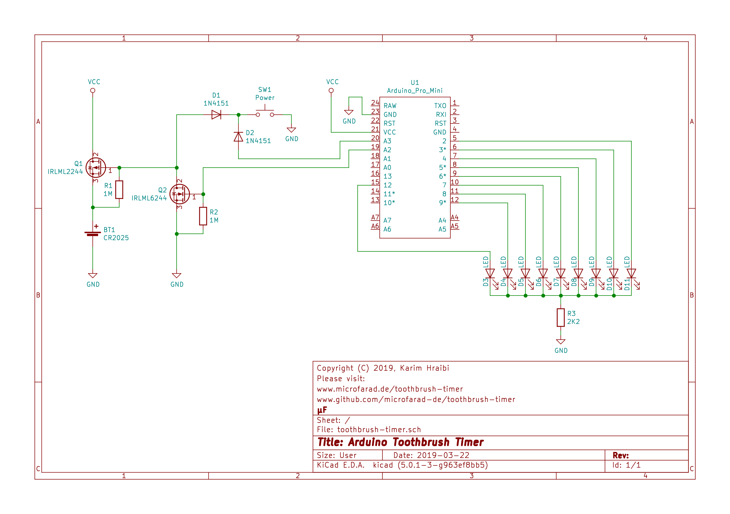
The soft power on circuit has been implemented around the field-effect transistors (MOSFETs) Q1 and Q2, resistors R1 and R2, small signal diodes D1 and D2, and tactile switch SW1. Briefly pressing SW1 would connect the gate of the MOSFET Q1 to the power supply ground through D1, this will cause the N-channel MOSFT Q1 to turn on and connect the positive battery terminal to the VCC rail. The Arduino will then boot up and apply the VCC voltage to the gate of the P-channel MOSFET Q2 via digital output pin A2 (analog pins on the ATmega328p can be configured as digital I/O pins). Q2 will stay on as long as the system is powered up and will continue pulling Q1‘s gate towards ground.
Please note that removing Q2 and directly feeding Q1‘s gate from the Arduino’s digital output pin is not a good option as it would result in some leakage current flowing from through Battery+ > R1 > (Arduino’s internal circuitry) > Battery-. Thus, the system would still consume some current (around 500 μA) while powered off.
The Arduino can power off itself anytime by setting the pin A2 to low; thus, turning off both Q1 and Q2 and disconnecting VCC from the battery positive terminal. The pull-up resistor R1 and pull-down resistor R2 are required for keeping both MOSFET gates discharged during the power off state, failing to do so may cause the MOSFETs to spontaneously turn on due to surrounding electrical noise. These resistors have a very large value of 1 megaohm in order to reduce the idle power consumption (approx. 5 μA for the current implementation).
The Arduino senses the state of the tactile switch SW1 via diode D2 on pin A3 which is configured as digital input. Pressing SW1 will cause pin A3 to be set to low. An internal pull-up resistor on pin A3 will cause it to go high as soon as SW1 gets released. This functionality enables the use of SW1 for different purposes while the system is turned on.
9 low power LEDs D3 thru D11 are connected to their respective digital output pins on the Arduino. All of the LEDs share one common dropper resistor R3 which significantly reduces the number of parts to be installed on the little available PCB area. The drawback of this design is that only one single led can be turned on at any moment in time; thus, the LEDs need to be driven via multiplexing as described further above in this article.
Downloads
Among others, below you can find GitHub download links for the Arduino firmware source code and the KiCad schematic source files. All of the source code is distributed under the GNU General Public License v3.0.
Please note that the current implementation requires the customized Arduino bootloader found under the link below. For more details, please follow the installation instructions found within the README file on GitHub.